Introduction
Welcome to the universe of modular synthesis, a realm where sonic possibilities are only limited by your imagination. At its core, modular synthesis is about exploring, experimenting, and pushing boundaries. It's about creating unique sounds, textures, and musical expressions by interconnecting various modules in innovative ways. This manual is designed to be your guide on this fascinating journey.
In the world of electronic music, modular synthesis stands out as one of the most flexible and intricate systems for sound generation and manipulation. Instead of a fixed signal path, which you'd find in a traditional synthesiser, a modular setup allows users to patch different components (or modules) together in virtually infinite combinations. Each module performs a specific function be it generating sound, processing signals, or shaping control voltages and it's how you choose to combine and control these modules that define your sonic landscape.
Whether you're a seasoned sound designer looking to dive deeper, or a curious newcomer just starting out, this reference manual is here to assist. We've structured the content to provide both foundational knowledge and advanced techniques. From understanding the basics of oscillators, filters, and envelopes to exploring the nuances of advanced modulation and signal processing, this guide endeavours to cover every aspect of modular synthesis.
Remember, modular synthesis is as much an art as it is a science. It encourages trial and error, serendipitous discoveries, and happy accidents. While this manual will offer a structured approach to understanding the principles and techniques, never hesitate to break the rules and follow your intuition. The true magic of modular lies in the unexpected and the experimental.
So, get ready to embark on an auditory adventure, and let's dive deep into the electrifying world of modular synthesis!
The author generated this text in part with GPT-3, OpenAI's large-scale language-generation model. Upon generating draft language, the author reviewed, edited, and revised the language to their own liking and takes ultimate responsibility for the content of this publication.
User Interface
Overview
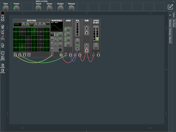
The user interface as shown above contains two distinct elements:
- The top Parameter bar; an area for macro controls, located at the top of the screen
- The main window; an area for making a patch from modular elements
- The contents of the main area can be selected by the tab on the right of the screen.
- Patching view; an area for making a patch from modular elements
- Performance panels such as the drum sequencer and the keys input device
- Menus relevant to the current area.
- Tabs on the right of the patching area, giving access to the module browser, settings and user manual.
Top Parameter Bar

Overview
The Top Parameter bar is a common location continuously viewable where any parameter from the modules used within your modular patch can be mapped for easy access from any view.
- To assign controls to the top parameter bar, click the edit icon in the top right. The strip will become shaded red to indicate entering Edit Mode. While in this mode, current contained parameter widgets are not accessible.
- To assign a parameter control to a cell, click a cell while the toolbar is shaded red. The individual cell turns a brighter red indicting selection. Then simply click on any parameter you wish to assign and the selection will be shown. This will mimic the same type of controller and range as the selected.
- To delete a selection simply double click on a cell while in edit mode.
- To exit Edit Mode click the edit icon located to the top right, and the bar will no longer be red.
Main Window
The content of the main window can be selected by the tab on the right of the screen. The main window can contain the following views:
Patching area, and when playable modules are added to the patch, a performance panel will be available.
Patching Area
Patching in the world of modular synthesis, is the process of connecting the individual modules together into configurations to produce the sound desired. Patches can be as simple as just a few modules, or can grow to represent larger ensembles.
Module Browser
Overview
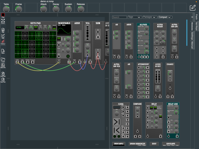
In the physical world, modules will be in fixed locations within a case and connected with cables. In the virtual world, the case starts with just an “Audio In/Out” module, and other modules can be selected from the “Modules” tab. These can be moved onto the patch by double tap, or drag and drop to the selected location.
Cables
Overview
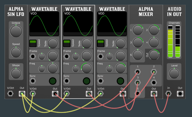
The Ports on the modules, like in the physical world, are connected by cables. Output ports are annotated by a solid white box around the port. An output can be connected to many places, but an input can be fed from only a single source.
To start a new cable, press and hold on a port, then drag your finger and a cable will appear connected to that port. If the floating end of the cable is dragged over a port it can be connected to, the port indicator is enlarged. Stopping the drag operation while over an enlarged port connects the cable.
If you wish to move an existing cable, just start dragging it from the end you wish to move. If you wish to remove the cable completely, start the move operation and drop the cable anywhere that is not a port.
The colour of the cables does not affect the processing but are there to aid humans. To select the cable colour click on the coloured jack icon in the menu, the menu will offer a selection of five colours to choose from. These default colours can be changed in the settings tab. While there are a few variations on colour standards (some using all five available), there are only four used in this document and tutorial, and they are:
- Red: Audio
- Yellow: V/Oct. Pitch
- Green: Triggers / Gates/ Clock
- Blue: Control Signals

Overview
The menus are located on one of the edges of the main area. This can be changed in the setting tab.
The menu contains:
- Start / Stop
- Pauses the audio engine. This is your emergency stop!
- Zoom
- The view change to show the complete patch. On larger patches this will appear as zoomed out.
- Selecting a module will zoom in.
Submenus, File, Edit, Colour
- File
- New
- Starts a new patch, uses the default template set in the settings, or just an “Audio in out” module.
- Load
- Save as
- Load Row
- Loads a saved row into the row below the one currently selected.
- Save Row
- Saves a single row, using the currently selected module. This can then be loaded in future patches for reuse.
- Edit
- Undo
- Redo
- Clone
- Makes a duplicate of the currently selected module, with the parameter settings preserved.
- Clone with cables
- Similar to Clone but, where possible, clones the connected cables.
- Erase
- Remove the currently selected module.
- Random
- Randomises the parameters of the currently selected module.
- Reset
- Resets the parameters on the currently selected module.
- Insert row
- Adds a blank row, below the currently selected module.
- Delete Empty Rows
- Removes all empty rows from the patch.
- Delete Row
- Deletes the row containing the currently selected module.
- Colours
- The five colours assigned to the cables. These can be changed in the settings tab.
Tabs
The patching area tabs are located on on of the sides. X will close the tabs. The tabs are resizable by dragging the edge.
Modules Browser
Here are where all the modules can be found.
The top edge of the Module library contains a search bar, where we can search with text, or select from a list of tags.
Manual
This document is viewable within the app.
Module Reference
Interface
Interface modules connect the virtual world to the physical world.
Audio In Out

Overview
The Audio In/Out Module is designed for a modular synthesiser setup. It provides a convenient interface for both inputting external audio into your modular system and outputting audio from your modular system. This module also includes a Level parameter and Polyphonic RMS meters for both the input and output signals, giving users real-time feedback on signal strength and integrity.
Front Panel Features:
- Audio Input Jack: Accepts external audio signal.
- Audio Output Jack: Sends audio signal out of the module.
- Level Knob: Allows the user to adjust the volume or amplitude of the inputted/outputted audio signal.
- Input RMS Meter: A polyphonic Root Mean Square (RMS) meter which displays the average power of the input signal. Useful for ensuring signals are not too weak or too strong, potentially causing clipping.
- Output RMS Meter: A polyphonic RMS meter showing the average power of the output signal.
X - Y Pads
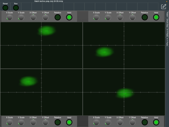
Overview
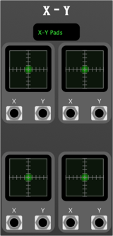
The 4 * X-Y Pad Module is a versatile and interactive component designed for modular synthesisers. It features four independent x-y pads, each with their own x and y outputs. Additionally, there is a separate full-screen playable area with customisable settings for offset and scale. Each pad supports relative movement and has configurable behaviours for holding the last position or returning to zero upon release.
Features
- Four Independent X-Y Pads:
- Each pad provides independent x and y control.
- Outputs: Each pad has two outputs (X and Y).
- Full-Screen Playable Area:
- Allows for detailed control with a larger interface.
- Adjustable Offset: Modify the starting point of the x-y pad.
- Adjustable Scale: Change the sensitivity and range of the x-y pad.
- Configurable Movement:
- Relative Movement: Enables the pad to recognise movements relative to the starting point.
- Position Hold: Each pad can either hold its last position or return to zero when released.
Operation
Using the X-Y Pads
- Standard Operation:
- Move your finger or stylus on the x-y pad to generate control voltage outputs at X and Y terminals.
- The position on the pad directly correlates to the voltage output.
- Relative Movement:
- Activate the Relative Movement Toggle to enable relative movement mode.
- In this mode, the pad recognises movements as relative changes from the initial touch point rather than absolute positions.
- Position Hold:
- Activate the Position Hold Toggle to keep the last position when you lift your finger or stylus.
- Deactivate this toggle to make the pad return to zero when released.
Using the Full-Screen Playable Area
- Adjust Offset:
- Use the Offset Control to set the desired starting point for the full-screen pad.
- Adjust Scale:
- Use the Scale Control to modify the sensitivity and range of the pad.
- Play:
- The larger area allows for more precise control, useful for detailed modulation.
Tips and Tricks
- Experiment with Different Settings:
- Try various combinations of offset and scale to find the perfect settings for your performance or recording.
- Use Relative Movement for Smooth Transitions:
- Relative movement can help achieve smoother transitions and more dynamic modulations.
- Utilise the Position Hold Feature:
- For sustained modulations, the position hold feature is invaluable, especially during live performances.
Oscillators
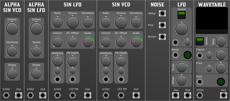
Overview
In a modular synthesiser, oscillators play a fundamental role in sound generation and shaping. Here's a detailed breakdown of the uses of oscillators in a modular synth:
- Sound Generation(VCO): At its most basic level, an oscillator in a modular synth produces a periodic waveform that is audible when sent to a speaker or headphones. Common waveforms include sine, sawtooth, square, and triangle waves. These raw waveforms are the building blocks of synthesised sound. Oscillators that operate in the audible range are often called VCO's (Voltage-Controlled Oscillators).
- Tone Modulation: Multiple oscillators can be combined to create rich and complex sounds. This is often done using FM (Frequency Modulation) or AM (Amplitude Modulation). For instance, the frequency of one oscillator can be modulated by the output of another to produce evolving timbres and tones.
- Low-Frequency Oscillator (LFO): Not all oscillators in a modular setup produce audio signals. LFOs produce waveforms at a frequency typically below the range of human hearing and are used to modulate other modules. For example, an LFO can be connected to a filter cutoff, amplitude, or even another oscillator's pitch to create movement and dynamics in the sound.
- Clock and Rhythm Generation: Oscillators can be used to produce clock signals which control the timing of sequencers, drum modules, or any other time-based component in the modular setup.
- Complex Oscillators: These are modules that internally use multiple oscillators to create a richer sound. They might incorporate wave shaping, folding, or other techniques to produce a wide palette of sonic possibilities.
- Tuning and Intervals: By controlling the pitch of oscillators, you can create musical intervals, chords, or even microtonal scales. With voltage-controlled oscillators (VCOs), the pitch can be adjusted by applying varying voltage levels.
- Noise Generation: While not periodic waveforms like the traditional oscillator shapes, some oscillators also produce white, pink, or other types of noise. Noise is essential for creating percussion sounds, wind sounds, or any other sound that requires a more random audio signal.
- Audio Rate Modulation: This is when an oscillator running at audio rates (i.e. speeds that produce audible frequencies) is used to modulate another part of the signal chain. This can lead to interesting sidebands and harmonics, producing unique textures.
- Feedback Loops: Oscillators can be incorporated into feedback paths where a part of the output is sent back to the input. This can lead to chaotic and unpredictable results, which can be interesting in experimental sound design.
- Physical Modelling: Some advanced modular systems might use oscillators in conjunction with other modules to emulate the behaviour of physical instruments, like plucked strings or blown pipes.
- In the world of modular synthesis, the possibilities are vast and often only limited by one's imagination. Oscillators are fundamental components, but the magic really happens in how they're patched and interact with other components.
Oscillator Basics
- For pitch control, oscillators typically have a 1V/Oct input.
Basic Principle: In a V/Oct system, a change of 1 Volt will result in a pitch change of one octave. So if you're playing a middle C note and you increase the control voltage by 1 Volt, the note will increase to the C one octave above.
Semitones: Since there are 12 semitones in an octave, each semitone corresponds to a change of 1/12 Volt, or approximately 0.08333 Volts.
Control Voltage Source: In a modular synthesiser, the V/Oct control voltage typically comes from a keyboard, sequencer, or other control device. For instance, when you press a key on a keyboard, it sends a specific voltage to the V/Oct input of an oscillator module. The oscillator then generates a tone at the corresponding pitch.
Alpha Sin VCO & Alpha Sin LFO
Overview
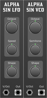
The Alpha Sin VCO is a voltage-controlled oscillator that produces a sine wave that can be morphed into many shapes. It is one on the entry level oscillators in the system, it has limited controls and is easy to use. All instances have unique tuning, a small offset less than two cents, so you can use multiple instances to create chords and other harmonies.
- V/Oct (Voltage per Octave): Controls the pitch of the VCO. Every volt increase will double the frequency (one octave up).
Outputs
- Audio: The main audio output, sending the waveform generated by the VCO.
Parameters
- Octave: Adjusts the base frequency in octave steps.
- Semitone: Adjusts the frequency in semitone steps.
- Shape: This parameter morphs the waveform from one shape to another, allowing the user to sculpt the tone.
Controls & Functions
Octave Control
- This knob allows users to shift the frequency range of the VCO over multiple octaves. Turning the knob clockwise increases the pitch, while counter-clockwise decreases it.
Semitone Control
- The Semitone control provides finer frequency adjustments within an octave. By turning the knob, you can increase or decrease the pitch in semitone increments.
Shape Control
- The Shape control is a multi-functional parameter that alters the waveform being generated. Starting from a sine wave at the lowest setting, turning the knob will progressively morph the waveform through various shapes with increasing harmonic intensity. The exact waveform at any given position will depend on the design and implementation of the VCO.
Applications & Usage Tips
- Melodic Sequences: By feeding a varying voltage into the V/Oct input and adjusting the Octave and Semitone parameters, users can craft evolving melodic sequences.
- Sound Design: The Shape parameter can be modulated with an external CV source to create evolving timbres and textures, ideal for pads, soundscapes, and other atmospheric sounds.
- External Modulation: For dynamic performances, consider modulating the V/Oct input with an external sequencer, LFO, or envelope generator. This will allow the VCO to produce varying pitches or tones based on the external input.
Sin VCO & Sin LFO
Overview
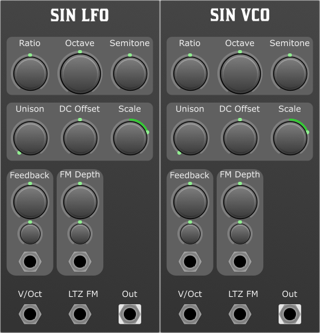
Sin VCO is the fully featured version of the Alpha Sin VCO. It has more controls and features, allowing for more complex control and sound manipulation. All instances have unique tuning (a small offset of less than two cents), so you can use multiple instances to create chords and other harmonies.
Parameters
- Ratio: This parameter defines the fundamental frequency's harmonic or sub-harmonic ratio. A ratio of 1:1 would keep the fundamental frequency unchanged, whereas 2:1 would double it, and 1:2 would halve it.
- Octave: Adjusts the pitch in increments of octaves. Turning this control will shift the pitch by 12 semitones at a time.
- Semitone: Allows fine-tuned pitch adjustments in semitone steps.
- Unison: Layers multiple instances of the current waveform to produce a thicker and richer sound. The unison parameter determines the number of voice layers. When set to any value above 1, polyphony is traded for unison.
- DC Offset: Introduces a direct current offset to the waveform, shifting it up or down along the vertical axis.
- Scale: Adjusts the amplitude of the waveform, effectively controlling its volume.
- Feedback: Determines the amount of the oscillator's output that's fed back into its input, introducing harmonic complexities.
- Feedback CV Attenuverter: Controls the strength and polarity of an external CV (Control Voltage) source affecting the feedback parameter.
- FM Depth: Controls the amount of frequency modulation (FM) applied to the oscillator when an external FM source is connected.
- FM Depth Attenuverter: Adjusts the strength and polarity of an external CV source affecting the FM Depth.
- V/Oct: The primary pitch control input. Each 1V increase corresponds to a one-octave increase in pitch.
- Linear Through Zero FM: An input designed for frequency modulation. In "through-zero" FM, the carrier oscillator can be modulated to a point where it stops (zero frequency) and then continues in the opposite phase.
- Feedback: External input to control the feedback amount, allowing for dynamic adjustments via external modulation sources.
- FM Depth: External input to adjust the FM Depth parameter, granting dynamic modulation capabilities.
Usage Guidelines
- Start by connecting a sequencer's V/Oct output to the VCO's V/Oct input. This sets up basic pitch control.
- Introduce FM modulation by connecting an LFO or another VCO to the Linear Through Zero FM input and adjusting the FM Depth and FM Depth Attenuverter.
- Experiment with feedback by turning the feedback knob or by introducing an external modulation source to the Feedback input, adjusting with the Feedback CV Attenuverter.
- Layer voices with the Unison control for a richer sound.
- Utilise the Ratio, Octave, and Semitone parameters to fine-tune the VCO's pitch.
- Use the DC Offset to introduce creative shifts to the waveform and the Scale parameter to adjust the output volume.
Noise

Overview
The Noise Module is an essential tool for the modular synthesist, offering a selection of noise colours vital for various applications ranging from sound design to rhythmic modulation. This module offers three distinct noise outputs: White, Pink, and Red (also known as Brownian).
Features
- White Noise: Equal energy per frequency band, giving a consistent hiss sound, perfect for percussive sounds and high-frequency content.
- Pink Noise: Equal energy per octave, resulting in a balanced sound often perceived as even across frequencies. Suitable for creating smooth textures or imitating natural phenomena.
- Red (Brownian) Noise: Energy decreases as the frequency increases. This gives the noise a deep, rumbling character, which is excellent for bass-heavy textures and low-frequency content.
Front Panel Controls
The design is kept minimalistic, focusing on providing noise outputs without any parameters to adjust.
- White Noise Output: Jack output for white noise.
- Pink Noise Output: Jack output for pink noise.
- Red Noise Output: Jack output for red (Brownian) noise.
Tips and Tricks
- Percussive Elements: White noise is an excellent source for creating snare drums or hi-hats in a modular setup. Send the white noise through an envelope-controlled VCA for dynamics and a filter to shape the sound further.
- Natural Textures: Pink noise can mimic many natural processes like rain or wind when combined with reverb or spatial effects.
- Deep Backgrounds: Use Red noise as a foundation or backdrop for drone-based music, giving a warm and deep atmosphere.
- Modulation Source: Even though it's inherently unpredictable, noise can be a fascinating source for modulation. For example, patching red noise into a filter's cutoff can simulate the random fluctuations you might hear in analog gear.
LFO

Overview
The Gordon-Smith Quadrature LFO (Low-Frequency Oscillator) module is a versatile and powerful tool designed for modular synthesisers. It implements the Quadrature Oscillator with additional features for flexibility and creative control over modulation in your modular setup.
Features
- Quadrature Oscillator Implementation: The module features the renowned Gordon-Smith Quadrature Oscillator, providing two simultaneous LFOs for versatile modulation possibilities.
- Default Speed: The default speed of the LFO is set to C-3, which corresponds to approximately 2.044Hz or a cycle duration of 0.489 seconds.
- Tuning Parameter: The module allows tuning within a range of ±5 octaves, providing a wide spectrum of frequency options.
- Slow Switch: An optional slow switch is provided, allowing you to reduce the timing by an additional 5 octaves, effectively slowing down the LFO. This results in a cycle duration of 8 and a half minutes. External control voltage (CV) can be used to further extend the cycle duration.
Front Panel Controls
Parameters:
- Speed Switch: Allows you to toggle between the default speed and the slow mode.
- Duration: Sets the cycle duration of the LFO. The default speed is set to C-3, which corresponds to approximately 2.044Hz or a cycle duration of 0.489 seconds. The slow mode reduces the timing by an additional 5 octaves, resulting in a cycle duration of 8 and a half minutes.
- Duration CV Attenuverter: Controls the effect of external CV on the cycle duration.
- Reset Push Button: Manually resets the phase of the LFO.
- Output Scale: Adjusts the amplitude of the LFO output.
- Output Offset: Shifts the DC offset of the LFO output.
Inputs:
- Duration: CV input for controlling the cycle duration. Polyphony count is determined by the number of channels provided at this input.
- Reset: Allows manual resetting of the LFO phase.
Outputs:
- Sine: Outputs the sine wave of the LFO.
- Cosine: Outputs the cosine wave of the LFO.
WaveTable
Overview
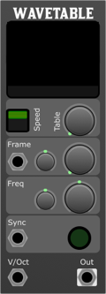
The Wavetable Oscillator Module is an innovative addition to modular synthesisers, offering unparalleled flexibility and creative control over sound design. With its core functionality based around wavetable synthesis, this module enables users to select from a variety of preset wavetables or define their own unique wavetable via an intuitive drag-and-drop interface. This document outlines the features, parameters, inputs, and outputs of the Wavetable Oscillator Module.
Wavetables
Parameters
- Speed Selector:
- Offers three modes of operation, allowing the module to function across different ranges of frequency modulation:
- VCO (Voltage-Controlled Oscillator): Standard audio-rate oscillator function.
- LFO (Low-Frequency Oscillator): Operates at lower frequencies for modulation purposes.
- Slow: Ultra-low frequencies, ideal for evolving soundscapes and textures.
- Frame:
- Navigate through different frames (single-cycle waveforms) within the selected wavetable to find the perfect sound.
- Frame CV (Control Voltage):
- Modulate the frame selection with an external control voltage for dynamic waveform changes.
- Freq (Frequency):
- Adjust the base frequency of the oscillator.
- Freq CV (Frequency Control Voltage):
- Modulate the frequency with an external control voltage for vibrato, FM (Frequency Modulation), and other effects.
- Sync:
- Hard sync input for synchronising the phase of the oscillator with an external clock, creating rhythmic or timbral effects.
- Frame:
- CV input for modulating the frame selection, allowing for dynamic movement through the wavetable.
- Sync:
- Accepts a trigger or gate signal to reset the oscillator's phase, useful for sync effects or rhythmic modulation.
- VOct (Volt per Octave):
- Standard pitch control input, modulating the oscillator's frequency in tune with the standard 1V/oct scale.
Outputs
- Signal:
- The main audio output of the module, emitting the synthesised waveform based on the selected wavetable, frame, and all modulation parameters.
Usage Guidelines
- Modulation: Connect CV sources to the 'Frame', 'Sync', and 'VOct' inputs to modulate the wavetable oscillator dynamically. Use the 'Frame CV' and 'Freq CV' to add movement to your sound.
- Tuning: Adjust the 'Freq' parameter to set the base frequency. Fine-tune the pitch modulation with the 'VOct' input for precise pitch control.
- Output: Connect the 'Signal' output to your modular system's signal chain to integrate the wavetable oscillator's output into your patch.
- Experimentation: Explore the effects of different modulation sources, sync options, and wavetable/frame selections to discover the vast sonic possibilities of the Wavetable Oscillator Module.
Drums
Drum Sample
Overview
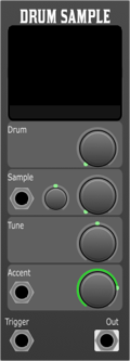
The Drum Sample Player Module is a versatile addition to any modular synthesiser setup, designed for both live performance and studio work. It combines the classic feel of natural drum sounds with the flexibility and breadth of electronic percussion. With an intuitive interface and a wide range of features including a waveshape display and extensive sample selection, this module offers unparalleled control and creativity in crafting your drum sounds.
Parameters
- Drum Type:
- Select the category of drum sound.
- Sample:
- Choose the specific sample within the selected drum type.
- Sample CV Attenuverter:
- Fine-tune the control voltage (CV) affecting the sample selection for dynamic performance changes.
- Tune:
- Adjust the pitch of the selected drum sample for perfect integration into your track.
- Accent:
- Control the intensity of the drum hit for dynamic performances.
- Sample CV:
- Control Voltage input for real-time sample selection modulation.
- Accent Trigger:
- External trigger input for accentuating specific drum hits.
- Trigger:
- Primary trigger input for activating the drum sound.
Outputs
- Signal Out:
- The audio output of the selected drum sample, ready to be integrated into your mix.
Usage
- Basic Operation
- Selecting a Drum Type and Sample:
- Use the Drum Type knob to scroll through the available drum categories.
- Once a category is selected, use the Sample knob to navigate through the different samples within that category.
- The selected sample's waveform will be displayed on the Waveshape Display.
- Modulating Sample Selection:
- Connect a CV source to the Sample CV input.
- Use the Sample CV Attenuverter to adjust the depth of the modulation effect on the sample selection.
- Tuning and Accentuation:
- Adjust the Tune knob to set the pitch of the drum sound.
- Connect an external trigger to the Accent Trigger input to dynamically accentuate specific drum hits.
- Advanced Usage
- Experiment with dynamic modulation by connecting LFOs, sequencers, or envelope generators to the Sample CV and Accent Trigger inputs for evolving textures and rhythms. Utilise the Signal Out in conjunction with effects modules to further sculpt and enhance your drum sounds.
Amplifiers & Attenuators
Attenuators:
In a modular synthesiser, an attenuator is a module or function that reduces the amplitude or voltage of a signal. This can be particularly useful when you want to scale down the intensity or strength of a modulation source. For instance, if a modulation source is producing a signal that is too strong for the desired effect on its target, an attenuator can be used to decrease its impact.
Attenuverters:
An attenuverter is a more versatile tool than a simple attenuator. It allows the user to both attenuate (reduce) and invert the phase of a signal. The inversion capability means that a positive voltage can be turned into a negative one and vice versa. This is especially useful in modular synthesis where you might want to flip the polarity of an envelope or an LFO to achieve different modulation effects. By turning the knob of an attenuverter, you can go from full positive voltage, through zero, and into full negative voltage, giving a wide range of control over the modulation source.
In essence, both tools allow for more precise control of modulation sources in a modular synthesiser, with attenuverters providing an added layer of flexibility by inverting signals.
In a Modular synth, A Voltage Controlled Amplifier (VCA) is a module that allows you to control the amplitude of a signal. This is typically done by applying a control voltage (CV) to the VCA, which then determines the amplitude of the output signal. The VCA is a fundamental component in modular synthesis, as it allows users to control the volume of signals in the signal chain. For instance, an envelope generator can be connected to a VCA to control the volume of a sound over time. This is how you can create the classic ADSR (Attack, Decay, Sustain, Release) envelope effect.
VCA

Overview
The Voltage Controlled Amplifier (VCA) is a fundamental building block in any modular synthesiser system. The VCA module in our system provides a means to control the amplitude or volume of an audio or CV signal based on another CV (control voltage) input. Furthermore, it comes with a built-in polyphonic RMS meter which gives users real-time feedback on the RMS (Root Mean Square) levels of the signals passing through the VCA, making it especially useful for polyphonic patches.
Front Panel Overview
Controls:
- Level Knob: Adjusts the initial or base level of the VCA. When fully counter-clockwise, the output is essentially muted. As you turn clockwise, the level increases.
- Level CV Attenuverter: This knob adjusts the amount and polarity of the control voltage's influence on the VCA's level. When centred, there's no modulation. As you turn it clockwise, you increase positive modulation, and counter-clockwise introduces negative modulation.
Jacks:
- Signal Input: The main audio or CV input of the VCA.
- Level CV Input: This is where you feed the control voltage that will modulate the amplitude of the signal input.
- Signal Output: The output of the VCA, post modulation.
Additional Features:
- Polyphonic RMS Meter: Displays the RMS value for each voice in a polyphonic patch, allowing users to visually monitor the amplitude dynamics of their signals.
Usage
- Basic Amplitude Control:
- Connect the signal you wish to control to the Signal Input.
- Adjust the Level Knob to set your desired base amplitude.
- Monitor the output using the Signal Output.
- Dynamic Amplitude Modulation:
- Follow the basic amplitude control steps.
- Connect a modulation source (e.g., an LFO, envelope, or sequencer) to the Level CV Input.
- Adjust the Level CV Attenuverter to set the depth and direction of modulation.
- Polyphonic Patch with RMS Feedback:
- In a polyphonic setup, connect all your polyphonic voice sources to the Signal Input.
- As your voices play, the Polyphonic RMS Meter will provide a visual representation of the amplitude for each voice. This is especially useful for balancing levels across different voices.
Tips and Tricks
- Tremolo Effect: Use a low-frequency oscillator (LFO) as the CV source for the Level CV Input to create a tremolo or amplitude modulation effect.
- Ducking/Sidechain Compression Effect: Use the envelope of a kick drum or other percussive element as the CV source for the Level CV Input to make other elements "duck" in volume when the kick hits.
- Make Use of Negative Modulation: By turning the Level CV Attenuverter counter-clockwise, you can introduce inverse modulation, causing the VCA to decrease in level with increased CV.
Troubleshooting
- No Sound: Ensure that your Signal Input is correctly patched, the Level Knob isn't turned all the way down, and your external gear (speakers, headphones) is correctly set up and powered on.
- No Modulation: If you've patched a source into the Level CV Input but aren't hearing any modulation, ensure that the Level CV Attenuverter isn't set to its middle (neutral) position.
- Polyphonic RMS Meter not Displaying All Voices: Ensure that all your voices are actively producing sound. If a voice isn't active, its RMS value might be too low to register on the meter. The number of channels shown on the meter reflect the number of voices currently active.
Conclusion
The VCA module is an essential tool for sound sculpting, giving you dynamic control over the amplitude of your signals. Whether you're shaping the dynamics of a simple monophonic patch or crafting intricate polyphonic textures, the added bonus of the polyphonic RMS meter ensures you always have a clear visual representation of your sonic landscape.
Attenuvert
Overview:
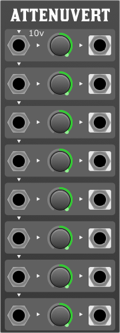
The 8-Channel Modular Synth Attenuverter is a powerful tool for electronic musicians, sound designers, and modular synth enthusiasts. It allows for precise control over input signals, expanding the possibilities for sound manipulation and modulation. With its normalisation feature, users can seamlessly route signals through multiple channels with ease.
Features:
- 8 Channels: Each channel has its own input, output, and control knob.
- Normalisation: Each channel is normalised to the previous channel's input. Channel 1 is normalised to a default 10V.
- Attenuvert: Each channel can attenuate (reduce) or invert (flip) the incoming signal.
Front Panel Controls:
- Input Jacks (1-8): These are where you connect the signal you wish to attenuate or invert.
- Output Jacks (1-8): These provide the attenuverted signal for each respective channel.
- Control Knobs (1-8): Rotate these knobs to adjust the attenuation or inversion of the signal. Centre position (12 o'clock) gives 0V output. Rotating the knob counter-clockwise from centre attenuates the signal, while rotating it clockwise inverts and boosts it.
Usage:
- Basic Attenuverting:
- Connect the desired signal to the input jack of any channel.
- Rotate the corresponding knob to adjust the strength or inversion of the signal.
- Patch the output jack to your desired destination.
- Using Normalisation:
- Connect your primary signal to the input of Channel 1.
- Without patching any further inputs, each subsequent channel will automatically use the input from the previous channel (due to normalisation). For instance, if you only patch into Channel 1, Channel 2 will use Channel 1's input, Channel 3 will use Channel 2's input, and so on.
- Patch from the output jacks of any channels you wish to use.
- Adjust each channel's knob for desired attenuation or inversion.
- Breaking Normalisation:
- Simply patch a new signal into any channel's input to break the normalisation chain. For example, if you patch signals into Channels 1 and 3, Channel 2 will still be normalised to Channel 1, but Channel 4 will be normalised to Channel 3.
Envelope Generators
Overview
In the mesmerising world of modular synthesisers, where sonic landscapes can be sculpted with unparalleled freedom, the envelope generator stands as an essential module for shaping the dynamic contour of a sound. At its heart, an envelope generator crafts the evolution of a sound's amplitude over time, rendering life to otherwise static tones, giving them movement, expression, and character.
Imagine striking a piano key. The sound doesn't simply begin at its maximum loudness and abruptly end. Instead, it rises quickly to a peak, decays to a sustain level as the key is held down, and eventually, once the key is released, it fades away. This progression—attack, decay, sustain, and release, commonly referred to as ADSR is a classic representation of what an envelope generator can achieve. However, in the modular realm, the possibilities extend far beyond just this.
With the modular approach, envelope generators are not just limited to controlling volume. They can be connected to modulate filters, pitch, pulse width, or any other parameter available in the system. The envelope, in essence, becomes a modulator providing a user-defined voltage that changes over time based on its settings. When one grasps this concept, it becomes clear how crucial the envelope generator is in the modular setup.
So, as we delve deeper into the intricacies of modular synthesis, let us pay homage to the humble envelope generator. It's not just a tool for dynamics, but a versatile modulator that, when utilised creatively, becomes a gateway to uncharted sonic territories.
ADSR

Overview
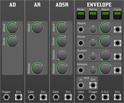
The ADSR (Attack, Decay, Sustain, Release) module is an envelope generator for modular synthesisers. It is used to shape the amplitude of an audio signal over time, allowing for the creation of dynamic and expressive sounds. The ADSR responds to a gate input and produces an envelope output that can be used to control various aspects of a sound, such as volume, filter frequency, or any other parameter in the synthesiser that accepts control voltage.
Parameters:
- Attack:
- Description: The duration it takes for the envelope to rise from zero to its maximum level after a gate signal is received.
- Usage: Turning the knob or adjusting the control increases or decreases the attack time. A shorter attack results in a quicker rise, creating a sharp or percussive onset to the sound. A longer attack gives a slow fade-in, resulting in a soft or pad-like onset.
- Decay:
- Description: The time it takes for the envelope to fall from the maximum level to the sustain level, after the attack phase has finished.
- Usage: Adjusting the decay parameter affects how quickly the sound will diminish after the initial attack. Short decay times can make the sound plucky or percussive, while longer decay times will make it seem like it is fading out before reaching the sustain level.
- Sustain:
- Description: The level at which the envelope will hold as long as the gate input is maintained. This is not a duration, but rather an amplitude level.
- Usage: Adjusting the sustain parameter sets the steady-state level of the sound while the key or gate is held. A high sustain will maintain a loud sound, while a low sustain will produce a softer sound during the hold phase.
- Release:
- Description: The time it takes for the envelope to fall from the sustain level to zero, once the gate input is terminated.
- Usage: Adjusting the release parameter affects how long the sound lingers after the gate or key is released. A short release will make the sound stop abruptly, while a longer release will allow the sound to fade out gradually.
- Gate:
- Description: The control signal that triggers the ADSR envelope. When the gate signal is high (or "on"), the envelope will move through the Attack, Decay, and Sustain phases. When the gate signal goes low (or "off"), the envelope enters the Release phase.
- Usage: Connect a gate or trigger signal to this input, usually from a keyboard, sequencer, or other triggering device.
Outputs:
- Envelope:
- Description: The resulting shaped control voltage signal based on the ADSR settings.
- Usage: This output can be patched into any module or parameter that accepts control voltage, such as a VCA (Voltage-Controlled Amplifier), VCF (Voltage-Controlled Filter), or any other CV input.
Tips:
- For percussive sounds, set a short attack and decay with a low or zero sustain.
- For pad-like sounds, use a longer attack, a higher sustain level, and a longer release.
- Experiment with the interplay between decay and sustain to achieve evolving tones and textures.
Conclusion:
The ADSR envelope generator is a fundamental tool in the modular synthesis world. By understanding and mastering its parameters, you can craft a wide array of tonal shapes and dynamics to breathe life into your sounds.
AD

Overview
The AD (Attack, Decay) module is an envelope generator for modular synthesisers. It is used to shape the amplitude of an audio signal over time, allowing for the creation of dynamic and expressive sounds. The AD responds to a trigger input and produces an envelope output that can be used to control various aspects of a sound, such as volume, filter frequency, or any other parameter in the synthesiser that accepts control voltage.
Parameters:
- Attack:
- Description: The duration it takes for the envelope to rise from zero to its maximum level after a gate signal is received.
- Usage: Turning the knob or adjusting the control increases or decreases the attack time. A shorter attack results in a quicker rise, creating a sharp or percussive onset to the sound. A longer attack gives a slow fade-in, resulting in a soft or pad-like onset.
- Decay:
- Description: The time it takes for the envelope to fall from the maximum level to the sustain level, after the attack phase has finished.
- Usage: Adjusting the decay parameter affects how quickly the sound will diminish after the initial attack. Short decay times can make the sound plucky or percussive, while longer decay times will make it seem like it’s fading out before reaching the sustain level.
- Gate:
- Description: The control signal that triggers the ADSR envelope. When the gate signal is high (or "on"), the envelope will move through the Attack, Decay, and Sustain phases. When the gate signal goes low (or "off"), the envelope enters the Release phase.
- Usage: Connect a gate or trigger signal to this input, usually from a keyboard, sequencer, or other triggering device.
Outputs:
- Envelope:
- Description: The resulting shaped control voltage signal based on the AD settings.
- Usage: This output can be patched into any module or parameter that accepts control voltage, such as a VCA (Voltage-Controlled Amplifier), VCF (Voltage-Controlled Filter), or any other CV input.
Tips:
- For percussive sounds, set a short attack and decay.
AR

Overview
The AR (Attack, Release) module is an envelope generator for modular synthesisers. It is used to shape the amplitude of an audio signal over time, allowing for the creation of dynamic and expressive sounds. The AR responds to a gate input and produces an envelope output that can be used to control various aspects of a sound, such as volume, filter frequency, or any other parameter in the synthesiser that accepts control voltage.
Parameters:
- Attack:
- Description: The duration it takes for the envelope to rise from zero to its maximum level after a gate signal is received.
- Usage: Turning the knob or adjusting the control increases or decreases the attack time. A shorter attack results in a quicker rise, creating a sharp or percussive onset to the sound. A longer attack gives a slow fade-in, resulting in a soft or pad-like onset.
- Release:
- Description: The time it takes for the envelope to fall from the sustain level to zero, once the gate input is terminated.
- Usage: Adjusting the release parameter affects how long the sound lingers after the gate or key is released. A short release will make the sound stop abruptly, while a longer release will allow the sound to fade out gradually.
- Gate:
- Description: The control signal that triggers the ADSR envelope. When the gate signal is high (or "on"), the envelope will move through the Attack, Decay, and Sustain phases. When the gate signal goes low (or "off"), the envelope enters the Release phase.
- Usage: Connect a gate or trigger signal to this input, usually from a keyboard, sequencer, or other triggering device.
Outputs:
- Envelope:
- Description: The resulting shaped control voltage signal based on the AR settings.
- Usage: This output can be patched into any module or parameter that accepts control voltage, such as a VCA (Voltage-Controlled Amplifier), VCF (Voltage-Controlled Filter), or any other CV input.
Envelope
Overview
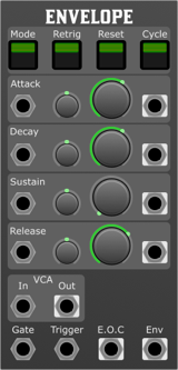
This envelope generator module is a versatile tool for a modular synth setup, providing different modes and extensive control over envelope shaping. With external control voltage (CV) inputs, each stage can be manipulated for maximum expressivity.
Modes
- ADSR: Traditional Attack, Decay, Sustain, Release envelope.
- AD: Attack and Decay only.
- AR: Attack and Release only.
Switches
- Retrig: Allows the envelope to be retriggered even if a previous envelope is still in progress.
- Reset: Resets the envelope to its starting state on next trigger.
- Cycle: When engaged, the envelope will loop continuously.
Parameters
- Attack: Controls the time it takes for the envelope to reach its peak after being triggered.
- Attack CV Attenuverter: Adjusts the amount of influence the Attack CV input has on the attack time.
- Decay: Controls the time it takes for the envelope to go from the peak to the sustain level.
- Decay CV Attenuverter: Adjusts the amount of influence the Decay CV input has on the decay time.
- Sustain: Sets the level at which the envelope will hold as long as the gate is high.
- Sustain CV Attenuverter: Adjusts the amount of influence the Sustain CV input has on the sustain level.
- Release: Controls the time it takes for the envelope to return to zero after the gate goes low.
- Release CV Attenuverter: Adjusts the amount of influence the Release CV input has on the release time.
- Attack CV: External control voltage input for the attack time.
- Decay CV: External control voltage input for the decay time.
- Sustain CV: External control voltage input for the sustain level.
- Release CV: External control voltage input for the release time.
- VCA: Control voltage input for overall envelope amplitude.
- Gate: Trigger input to start the envelope.
- Trigger: Input to start the envelope without waiting for a gate signal.
Outputs
- Attack Stage Gate: Outputs a gate signal during the Attack stage.
- Decay Stage Gate: Outputs a gate signal during the Decay stage.
- Sustain Stage Gate: Outputs a gate signal during the Sustain stage.
- Release Stage Gate: Outputs a gate signal during the Release stage.
- VCA: An internal VCA to shape signals
- E.O.C. (End of Cycle): Sends a trigger signal when the envelope has completed its cycle.
- Envelope: The main envelope output.
Usage
- Connect the Gate input to a keyboard or sequencer.
- Adjust the Attack, Decay, Sustain, and Release knobs to shape your desired envelope.
- Use the CV inputs to dynamically modulate each stage of the envelope.
- Connect the envelope output to control the amplitude of an oscillator, the cutoff of a filter, or any other module that accepts control voltage.
For cyclical modulation, engage the Cycle switch.
Tips
- The envelope generator is highly versatile and can be used to shape not only amplitude but also other parameters like filter cutoff, pitch, and more.
- Experiment with different modes (ADSR, AD, AR) for different musical contexts. AR mode can be especially useful for percussive sounds.
- The stage gate outputs can be used to synchronise other events in your modular setup with specific stages of your envelope. For example, you might trigger a sample or advance a sequencer every time the decay stage begins.
Conclusion
This envelope generator module is an essential tool in a modular synthesiser setup, offering a wide range of possibilities for sound shaping and modulation. Experiment with different modes, parameters, and connections to discover its full potential.
Reverbs
Overview
In the vast, intricate universe of modular synthesis, where sound manipulation is limited only by one's imagination, the reverb stands out as a transformative tool that adds depth, space, and dimension to the sonic landscape. But what exactly is reverb, and how does it function within the realm of a modular synth?
At its essence, reverb (short for 'reverberation') replicates the natural phenomenon where sound reflects off various surfaces before reaching our ears, creating a sense of space. Think of the lingering echoes you'd hear when clapping in an empty cathedral, or the subtle reflections of a voice in a cozy room. Reverb, in the context of music and sound design, simulates these spatial reflections, adding a layer of ambiance and character to the original sound.
In traditional instruments or audio gear, reverb might come in the form of built-in digital effects or external units. But in a modular synthesiser setup, reverbs are typically realised through dedicated modules. These 'reverb modules' can vary widely in complexity and functionality: from simple spring reverbs which physically emulate sound bouncing off springs, to advanced digital modules that can mimic diverse acoustic environments.
But why introduce reverb in a modular setting? For one, modular synths often generate very raw and direct tones. While these tones can be captivating in their own right, the introduction of reverb can turn a simple waveform into a vast sonic panorama, lending a sense of depth and context. This can be especially handy when crafting ambient landscapes, ethereal pads, or just adding a touch of 'air' to a lead or bass sound.
Furthermore, in a modular environment, where everything is interconnected and open to experimentation, reverbs aren't just end-of-chain effects. They can be dynamically controlled, modulated, and patched into other modules to create evolving textures and soundscapes. Want the reverb tail to morph over time? Patch an LFO into its size or dampening control. Interested in rhythmic reverberated bursts? Introduce a sequencer or gate patterns into the mix. The possibilities are endless.
In conclusion, reverb in a modular synth isn't just an effect... it's a sonic tool, a sculptor of space, and an enabler of ambient journeys. As you delve deeper into modular synthesis, you'll find that reverbs, with their echoing mystique, play a pivotal role in defining, refining, and expanding your aural horizons.
Plate Reverb
Overview
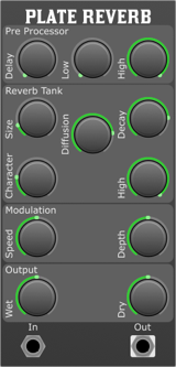
The Plate Reverb module for modular synthesisers is an advanced audio processing unit designed to simulate the reverberation effects of a large, vibrating metal plate. This module captures the lush, smooth, and richly textured sounds characteristic of classic plate reverb units, providing users with a wide range of sonic landscapes. From subtle ambiences to vast, immersive spaces, the Plate Reverb module brings depth and dimension to any audio signal. Importantly, this module sums all the input channels to a mono signal, and produces a two-channel pseudo-stereo output, enriching the spatial quality of the reverb effect and offering a wider, more immersive stereo field.
Parameters
- Pre Delay
- Controls the amount of time before the onset of the reverberation effect. This parameter allows you to adjust the spatial perception and distance of the sound source.
- Pre Low Cut
- Applies a high-pass filter to the input signal before it enters the reverb algorithm. This parameter helps in removing low-frequency content to avoid muddiness in the reverb tail.
- Pre High Cut
- Applies a low-pass filter to the input signal before it enters the reverb algorithm. This parameter is useful for darkening the sound or reducing high-frequency content to create a warmer reverb.
- Size
- Simulates the physical size of the metal plate, affecting the density and the initial build-up of the reverb sound. Larger sizes result in a bigger and more spacious reverb.
- Diffusion
- Controls the spread of the reverb reflections, affecting clarity and the texture of the reverb tail. Higher settings result in smoother and denser reverberation.
- Decay
- Adjusts the length of the reverb tail, controlling how long the reverb effect lasts after the initial sound has stopped.
- Tank Character
- Applies varying characters to the sound as it bounces about
- Tank High Cut
- Applies a low-pass filter to the reverb signal. This parameter allows you to control the brightness of the reverb tail.
- Modulation Speed
- Controls the speed of the internal modulation applied to the reverb tail, adding movement and a more natural feel to the effect.
- Modulation Depth
- Adjusts the amount of internal modulation applied to the reverb tail, affecting the depth and the intensity of the modulation effect.
- Wet
- Controls the volume of the processed reverb signal. Increasing this parameter will make the reverb effect more prominent.
- Dry
- Controls the volume of the unprocessed, original signal. Adjusting this parameter allows for a balance between the original sound and the reverb effect.
Usage
To integrate the Plate Reverb module into your modular synth setup, connect the output of your sound source to the input of the reverb module. Adjust the parameters as described above to tailor the reverb effect to your liking. The mix of the wet and dry signals can be finely tuned using the respective controls to achieve the desired balance in your audio mix.
Freeverb

Overview
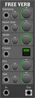
The "Freeverb" reverb module is a high-quality reverb effect unit for modular synthesisers, based on the renowned "Freeverb" algorithm. It offers extensive control over the reverb characteristics, with CV inputs for most parameters, allowing for dynamic modulation and integration into a modular synth environment.
Parameters and Controls:
- Damping:
- Adjusts the dampness of the reverb. Higher settings will produce a darker and more muted sound, while lower settings will create brighter reflections.
- Damping CV Attenuverter:
- Adjusts the amount of modulation received from the "Damping CV" input. At its centre position, there is no modulation. Turning clockwise increases positive modulation, and counter-clockwise increases negative modulation.
- Room Size:
- Determines the size of the virtual room for the reverb. Higher values will produce larger sounding reverbs.
- Room Size CV Attenuverter:
- Adjusts the amount of modulation received from the "Room Size CV" input.
- Width:
- Controls the stereo width of the reverb. At 100%, the reverb is wide and spacious. At 0%, it becomes mono.
- Width CV Attenuverter:
- Adjusts the amount of modulation received from the "Width CV" input.
- Freeze:
- When engaged, it freezes the reverb, creating a sustained ambient sound. Can be toggled on/off.
- Dry:
- Adjusts the level of the unprocessed signal. At 0%, only the reverb signal will be heard.
- Dry CV Attenuverter:
- Adjusts the amount of modulation received from the "Dry CV" input.
- Wet:
- Controls the level of the reverb signal. At 0%, no reverb signal will be heard.
- Wet CV Attenuverter:
- Adjusts the amount of modulation received from the "Wet CV" input.
- Damping CV:
- Control voltage input for modulating the damping parameter.
- Room Size CV:
- Control voltage input for modulating the room size parameter.
- Width CV:
- Control voltage input for modulating the width parameter.
- Freeze CV:
- Control voltage input to engage/disengage the freeze function. A positive voltage will typically activate the freeze.
- Dry CV:
- Control voltage input for modulating the dry mix.
- Wet CV:
- Control voltage input for modulating the wet mix.
- Audio In:
- Input for the audio signal you want to process with the reverb.
Outputs:
- Audio Out:
- Outputs the processed audio signal with the applied reverb effect.
Usage Tips:
- For subtle ambience, keep the "Room Size" small and the "Wet" level at a moderate setting.
- Engaging "Freeze" while playing can produce evolving soundscapes, especially with larger "Room Size" settings.
- The "Damping" control is particularly useful for tailoring the tonal character of the reverb. Adjust to taste based on the source material.
- Modulating the "Width" parameter can create interesting movement in a stereo mix.
Conclusion:
The Freeverb module is a versatile and expansive reverb solution for the modular synth environment. With its detailed controls and modulation capabilities, it allows users to craft a wide array of spatial effects, from subtle room ambiences to vast, expansive soundscapes.
Delays
Delay
Overview
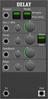
The Modular Synthesiser Delay Module is a versatile and powerful audio processing unit designed for creating intricate and expressive delay effects in your modular synthesiser setup. This stereo delay module features a range of controls and inputs to give you precise control over the delay parameters, allowing you to sculpt unique sonic landscapes.
The Delay module is polyphonic, using pairs of channels as stereo when used in ping pong mode. It is common practice to mix polyphonic notes into a mono signal using the sum module or a stereo signal using an audio mixer before applying the delay, as this both helps to glue the sound together, and reduces CPU consumption.
Parameters and Controls:
- Time:
- Sets the delay time, determining the duration between the original and delayed signals. This uses a V /Oct scale and when in slow mode, zero is set to C-3 2.044Hz. A setting of +1 will double the speed, and a setting of -1 will halve it. If the CV input is provided with the bpm level from the clock and the attenuverter is turned full clockwise, the delay will track the tempo. Try adjusting the time knob to both positive and negative integer values for standard beat divisions.
- Time Attenuverter:
- Adjusts the influence of external CV on the delay time. The attenuverter allows you to scale and invert the CV signal affecting the delay time. For clock synchronisation this should be turned fully clockwise.
- Speed Switch
- A switch to toggle between different delay speed settings. When in the slow position a time setting of zero has a delay time of 0.499 seconds for use as a standard time effect. When in the fast setting the delay is tuned about C4 261.61Hz and the delay can be used for pitched effects.
- Feedback
- Controls the number of repetitions in the delayed signal. Higher settings result in more feedback and a longer-lasting delay tail.
- Feedback Attenuverter
- Adjusts the impact of external CV on the feedback parameter. The attenuverter allows you to scale and invert the CV signal affecting feedback.
- Filter
- A DJ style filter in the feedback path, which is applied to each repetition. Turn anticlockwise for a lowpass to emulate natural decay, or turn clockwise for a high pass to create some space in the mix.
- Filter Attenuverter
- Modifies the effect of external CV on the filter parameter. The attenuverter allows you to scale and invert the CV signal affecting the filter.
- Dry / Wet
- Adjusts the balance between the original (dry) and delayed (wet) signals.
- Dry / Wet Attenuverter
- Controls the amount and direction of the CV (Control Voltage) affecting the Dry/Wet mix. The attenuverter allows you to scale and invert the CV signal.
- Freeze
- The Freeze control allows you to capture and sustain the incoming audio signal, creating a frozen texture.
- Mode
- Straight: Traditional delay mode with forward playback.
- Ping Pong: Stereo delay mode with alternating left and right playback.
- Freeze Input:
- Accepts a gate signal to activate or deactivate the freeze function externally.
- Dry/Wet Input:
- Accepts a CV signal to modulate the Dry/Wet mix.
- Time Input:
- Accepts a CV signal to modulate the delay time.
- Feedback Input:
- Accepts a CV signal to modulate the feedback amount.
- Filter Input:
- Accepts a CV signal to modulate the filter frequency.
- Audio Input:
- The input for the audio signal you want to process with the delay module.
Outputs:
- Audio Output:
- Delivers the processed audio signal with the applied delay effects.
Usage Tips:
- Classic Tape Delay Emulation
- Setup:
- Use a sequencer or an envelope generator to modulate the Time input.
- Set the Mode to Straight for a traditional delay effect.
- Adjust the Feedback for a classic tape delay sound.
- Apply a slight modulation to the filter frequency.
- Result:
- Achieve the warm and characterful sound of a vintage tape delay, with subtle pitch variations due to the modulated delay time.
- Rhythmic Delay Patterns
- Setup:
- Utilise a clock divider to rhythmically modulate the Time input.
- Set the Mode to Straight for clear rhythmic patterns.
- Experiment with different Speed Switch settings.
- Result:
- Generate rhythmic delay patterns synced to your modular system's clock, providing rhythmic interest and synchronisation with other elements in your setup.
- Experimental Soundscapes
- Setup:
- Apply random or chaotic modulation sources to the Time, Feedback, and Filter parameters.
- Set the Speed Switch to its fastest setting for unpredictable results.
- Use an external noise source as the Audio Input.
- Result:
- Explore the world of experimental sound design, where the delay parameters are constantly shifting, creating unpredictable and evolving sonic landscapes.
These examples showcase just a few possibilities, and the Modular Synthesiser Delay Module encourages exploration and creativity in designing your own unique delay effects. Adjusting parameters in real-time and experimenting with different modulation sources will yield a wide range of sonic possibilities.
Filters
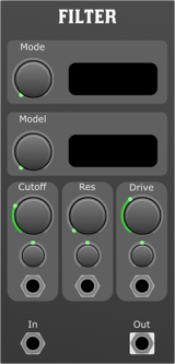
Overview
The realm of modular synthesis can appear labyrinthine to newcomers, with its maze of patch cables, knobs, and modules. However, at the heart of this intricate sonic landscape lies a set of foundational components that shape and mould the raw, electronic sounds into musical artistry. Among these vital components is the 'filter', an elemental tool that can dramatically sculpt and refine the auditory output of a modular system.
What is a Filter?
In the simplest terms, a filter in a modular synthesiser selectively attenuates or boosts certain frequencies from a sound signal. Think of it as an 'audio sieve', allowing some frequencies to pass through while holding back others. The result can range from subtle tonal changes to dramatic sound morphing.
Key Characteristics of Filters:
- Cutoff Frequency: This is the frequency around which a filter begins to take effect. Frequencies above or below this point, depending on the filter type, will be affected.
- Resonance: This controls the emphasis or peak around the cutoff frequency. Increasing resonance makes the filter 'ring' or 'resonate' at the cutoff frequency, producing a pronounced peak.
- Filter Types:
- Low-pass (LP): Allows frequencies below the cutoff to pass through, attenuating those above.
- High-pass (HP): Allows frequencies above the cutoff to pass through, attenuating those below.
- Band-pass (BP): Allows a band of frequencies around the cutoff to pass through while attenuating those outside this range.
- Notch (or Band-reject): Cuts out a band of frequencies around the cutoff, allowing frequencies outside this range to pass.
- Modulation: Many filters in a modular synth can be modulated by external sources, such as an envelope or a low-frequency oscillator (LFO). This allows for dynamic and evolving sound shaping.
Why are Filters Important in a Modular Synth?
In a modular setting, filters play a multifaceted role:
- Sound Shaping: They shape raw waveforms, like sawtooth or square waves, into more musically interesting and varied tones.
- Movement and Evolution: Through modulation, filters can impart movement to static sounds, making them evolve over time.
- Harmonic Control: Filters can be used to accentuate or diminish specific harmonics, thus modifying the timbral quality of a sound.
- Interactive Sound Design: The hands-on nature of modular synths allows for real-time filter adjustments, enabling interactive and spontaneous sound design.
In conclusion, filters are a cornerstone in modular synthesis. As you dive deeper into this world, understanding and mastering filters will enable you to craft sounds that are both unique and musically compelling. Embrace the journey of discovery and let the filter guide your sonic explorations!
Ladder Filter

Overview
The Multi-Mode Ladder Filter is a versatile module for a modular synthesiser setup, offering various filtering options that enable the user to shape the tonal character of the sound. Its multi-stage, non-linear waveshaping capability enriches the sonic possibilities, making it a vital module for sound design.
Modes
The filter offers six distinctive modes:
- Lowpass 12 (LP12)
- Lowpass 24 (LP24)
- Bandpass 12 (BP12)
- Bandpass 24 (BP24)
- Highpass 12 (HP12)
- Highpass 24 (HP24)
The numbers (12 or 24) refer to the filter's slope, indicating the rate of attenuation per octave.
Parameters
- Mode:
- Function: Selects the filter mode.
- Options: LP12, LP24, BP12, BP24, HP12, HP24.
- Model:
- Function: Chooses the specific non-linear waveshaping model.
- Options: Multiple, depending on the implemented waveshaping algorithms.
- Cutoff:
- Function: Sets the frequency at which the filter starts to act. In LP and HP modes, it defines the -3dB point.
- Cutoff CV Attenuverter:
- Function: Attenuates or inverts the incoming CV signal for the cutoff.
- Range: -100% (inverse) to 100% (full).
- Resonance:
- Function: Emphasises the frequencies around the cutoff point, adding a peak or "resonance" at that frequency.
- Range: Typically from 0 to self-oscillation.
- Resonance CV Attenuverter:
- Function: Attenuates or inverts the incoming CV signal for the resonance.
- Range: -100% (inverse) to 100% (full).
- Drive:
- Function: Applies gain to the input, pushing the filter into saturation and non-linear waveshaping territory for harmonic richness.
- Range: Typically from 0 (no drive) to maximum saturation.
- Drive CV Attenuverter:
- Function: Attenuates or inverts the incoming CV signal for the drive.
- Range: -100% (inverse) to 100% (full).
- Cutoff CV:
- Function: External control voltage input for dynamically modulating the cutoff frequency.
- Resonance CV:
- Function: External control voltage input for dynamically modulating the resonance amount.
- Drive CV:
- Function: External control voltage input for dynamically modulating the drive amount.
- Signal In:
- Function: Audio input to the filter.
Outputs
- Signal Out:
- Function: Filtered audio output.
Applications
- Sound Design: Use different modes and models for creating unique textures and timbres.
- Rhythmical Modulation: Modulate the cutoff with rhythmic CV sources to create pulsing, rhythmic textures.
- Saturation & Distortion: Use the drive parameter to add warmth and harmonic content.
Pitch Modulation
Vibrato

Overview
The Vibrato module is a pitch modulation effect for a modular synthesiser, designed to create a classic vibrato effect by modulating the pitch of an incoming audio signal. It offers a range of controls and inputs for shaping the vibrato effect, allowing for expressive and dynamic pitch modulation.
Parameters
- Depth
- Function: Adjusts the intensity or amount of modulation applied to the signal.
- Range: The Depth control allows for a wide range of modulation, from very subtle to extremely pronounced effects. Turning the knob clockwise increases the modulation depth.
- Depth CV Amount
- Function: Controls how much the Depth CV input affects the modulation depth.
- Range: This control allows for precise adjustment of the external control voltage influence on the Depth parameter. Turning the knob clockwise increases the sensitivity to the Depth CV input.
- Rate
- Function: Sets the speed at which the modulation occurs.
- Range: The Rate control spans a broad spectrum, from slow, evolving modulations to fast, vibrato-like effects. Increasing the rate is as simple as turning the knob clockwise. With the control in the 12 O'clock position the rate is set to 2.04Hz or 122.64 bpm.
- Rate CV Amount
- Function: Determines the extent to which the Rate CV input modulates the modulation rate.
- Range: This knob allows for the modulation speed to be dynamically controlled by an external voltage source, with clockwise adjustments increasing the CV input's impact on the Rate.
Depth CV
- Description: Accepts control voltage signals to modulate the Depth parameter externally. This input allows for dynamic control over the modulation depth, enabling more complex and evolving soundscapes.
Rate CV
- Description: Receives control voltage signals for external modulation of the Rate parameter. Utilising this input can introduce rhythmic variations or synchronise the modulation rate with other elements of your modular system. This is based on a 1 V/Oct scale, with 0V being C-3 2.044Hz, 122.64 bpm.
Signal In
- Description: The primary audio input for the module. The Signal In is where you feed the audio signal you wish to modulate with Vibrato's capabilities.
Outputs
Signal Out
- Description: Outputs the modulated audio signal. This output should be connected to your modular system's next stage, whether that be further processing modules or your system's main output.
Usage Tips
- Dynamic Modulation: Utilise the CV inputs for Depth and Rate to introduce dynamic changes to your sound. Modulating these parameters in real-time can create evolving textures and rhythms that breathe life into your patches.
- Experiment with CV Sources: Experimenting with different CV sources for the Depth and Rate CV inputs can lead to unique and unexpected modulation effects. Consider using LFOs, envelope generators, or sequencers as CV sources.
- Subtle to Extreme: Start with subtle settings for Depth and Rate to understand the module's impact on your sound. Gradually increase these settings to explore the full range of modulation Vibrato can provide.
Flanger
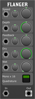
Overview
The Flanger/Chorus Module is a versatile effect module for modular synthesisers, capable of producing a wide range of time-based modulation effects from subtle chorus to intense flanging, alongside vibrato to add life to a performance.
Parameters
- Speed
- Control Range: Adjusts the rate of the LFO that modulates the delay time, influencing the frequency of the flanging or chorus effect.
- CV Input & Attenuverter: Modulate the speed externally via CV and adjust the modulation amount with the attenuverter.
- Depth
- Control Range: Sets the intensity of the modulation, affecting how much the delay time is varied by the LFO.
- CV Input & Attenuverter: Allows external modulation of depth and fine-tuning of the modulation depth via the attenuverter.
- Feedback
- Control Range: Controls the amount of the output signal fed back into the module's input, intensifying the flanging effect.
- CV Input & Attenuverter: External modulation of feedback is possible, with the attenuverter adjusting the feedback modulation depth.
- Dry
- Control Range: Adjusts the level of the unprocessed signal.
- CV Input & Attenuverter: Modulate the dry signal externally and fine-tune the modulation amount with the attenuverter.
- Wet
- Control Range: Adjusts the level of the processed (effect) signal.
- CV Input & Attenuverter: Allows for external modulation of the wet signal level, with the attenuverter providing precise control over modulation amount.
- Mono / Quadrature Switch
- Toggle between mono and quadrature LFO modes, offering either a singular mono effect or a spatial stereo effect that utilises pairs of stereo channels for immersive soundscapes.
Usage Tips
- Starting Point: Begin with the Dry/Wet mix at a balanced setting to hear both the original and effected signals. Gradually adjust the Speed, Depth, and Feedback to taste.
- Spatial Effects: Use the Mono / Quadrature switch to explore spatial audio effects. Quad mode requires a compatible quadraphonic audio setup.
- Creative CV Modulation: Experiment with dynamic control by patching LFOs, envelopes, or sequencers into the CV inputs. Use attenuverters to fine-tune the response to external modulation.
- Subtle Chorus: Use slow LFO speeds and low depth settings with no feedback for a subtle chorus effect that adds depth and warmth to your sound.
- Flanger Effect: Increase the LFO speed and depth to create a more pronounced flanging effect. Experiment with feedback to intensify the effect further.
- Vibrato: Set the Speed to a slow rate, the Depth to a moderate setting, 100% wet, 0% dry with no feedback for a classic vibrato effect.
Other
Compare

Overview
The Comparator Module is an essential component in modular synthesisers, offering versatile functionality for signal processing and modulation. By comparing an input signal against a set threshold, this module generates two distinct outputs based on whether the input signal is less than or greater than the threshold value. This capability makes it an invaluable tool for creating dynamic effects, gates, and modulation sources.
Parameters
- Threshold
- The Threshold parameter sets the reference level against which the input signal is compared. Signals with a voltage above this level are considered "greater," while signals below are deemed "less.".
- Adjusting this control manually sets the static threshold level. When used in conjunction with the Threshold CV Input and its corresponding attenuverter, dynamic control over the threshold level is possible, allowing for more complex and evolving soundscapes.
- Threshold CV Attenuverter
- This parameter controls the amount and polarity of the control voltage (CV) applied to the Threshold parameter.
- Turning the knob to the right of its midpoint increases the influence of the CV on the threshold, maintaining its polarity. Turning it to the left inverts the CV's effect and reduces its influence, allowing for precise control over the modulation depth and direction of the threshold level.
- Threshold CV
- Accepts a control voltage signal to dynamically modulate the Threshold parameter.
- Connect a CV source to this input to dynamically modulate the threshold level. The actual influence of the CV is further adjusted by the Threshold CV Attenuverter, allowing for enhanced control over how the input signal is compared to the threshold.
- Signal
- The primary audio or CV input that is compared against the threshold.
- Input the signal you wish to compare against the threshold level. This could be anything from a simple oscillator waveform to complex CV signals, offering a wide range of creative possibilities.
Outputs
- Less
- Outputs a gate signal when the input signal is less than the threshold. The gate is high ( +10V) when the condition is met and low (0V) otherwise.
- Use this output to trigger or control other modules when the input signal falls below the threshold. It's ideal for generating rhythmic patterns or activating effects in response to specific signal conditions.
- Greater
- Outputs a gate signal when the input signal is greater than the threshold. Similar to the Less Output, the gate is high when the condition is met and low otherwise.
- This output can be used to trigger or modulate modules when the input signal exceeds the threshold, allowing for dynamic control and interaction with the evolving musical material.
Usage
- Dynamic Gating:
- Use the Less and Greater outputs to create complex rhythmic patterns by gating different sound sources based on an input signal's amplitude.
- Envelope Following:
- Modulate the threshold with an envelope to create dynamic effects that respond to the amplitude of an input signal.
- Signal Routing:
- Use the outputs to route signals to different parts of your synthesiser based on their amplitude, creating evolving textures and patterns.
Slew

Overview
The Slew Module in a modular synthesiser is designed to smooth the transitions between voltages, effectively turning abrupt changes in voltage into gradual slopes. This process is often used to soften the edges of gate signals, convert square waves into more sinusoidal shapes, or create portamento/glide effects between notes.
Parameters
- Duration:
- This controls the amount of time it takes for the output voltage to catch up to the input voltage. A longer duration results in a slower transition from one voltage to another, creating a more pronounced glide or slew effect.
- Duration CV Attenuverter:
- This parameter allows for external control voltage (CV) modulation of the Duration parameter. The attenuverter adjusts the depth and polarity of this modulation. At its centre position, the modulation effect is neutral (i.e., no modulation). Turning the knob clockwise increases the positive modulation depth, while counterclockwise rotation introduces negative modulation, potentially reversing the modulation effect.
- Duration:
- This input accepts a control voltage signal to dynamically adjust the Duration parameter in real-time, allowing for complex and evolving modulation effects. The actual impact of the CV input is further refined by the Duration CV Attenuverter.
- Signal:
- This is the primary input for the signal that you wish to apply the slew effect to. It can accept any type of voltage signal, such as an audio signal, gate, trigger, or CV.
Outputs
- Signal:
- The module outputs the processed signal, which has been subjected to the slew effect based on the settings of the Duration and Duration CV Attenuverter, along with any real-time modulations applied through the Duration CV input.
Usage Tips
- Creating Glide Between Notes: Use the Slew Module to create a smooth transition between pitch CV signals for a portamento or glide effect.
- Softening Edges: Apply the module to square waves or gate signals to round off sharp edges, making them less abrupt.
- Dynamic Modulation: Experiment with dynamic control over the Duration parameter via the CV input to create evolving textures and timbres in your sound.
- Audio Rate Modulation: Although typically used for control voltages, try applying the Slew Module to audio-rate signals for unique effects.
Usage
- The Slew Module is versatile and can be used in various applications, including but not limited to:
- Synthesising more natural-sounding envelopes and LFO shapes.
- Creating legato effects between notes in a sequence.
- Smoothing out control voltages to avoid abrupt changes in parameters they control.
- Acting as a basic low-pass filter at audio rates, depending on the slew rate and input signal.
Recorder
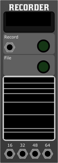
Overview
This module allows for the direct recording of audio signals from the synth into a high-quality WAV file, accommodating complex setups and performances with ease. It features four polyphonic signal inputs, capable of handling up to 64 channels in total, making it an ideal choice for capturing layered, rich textures and tones generated by your modular synth setup as a stereo file for consumption in an audio player or as a multichannel stems file for additional mixing and processing in a DAW.
Features
- Multiple Inputs:
- Four inputs are available, each capable of handling up to 16 channels, allowing a cumulative total of up to 64 channels to be recorded simultaneously to a single WAV file.
- Adaptive Width RMS Meters:
- The module includes RMS meters with adaptive width, providing visual monitoring of all input signals. These meters are designed to dim when not in recording mode, offering a clear, at-a-glance indication of the module's status.
- DC Coupled:
- Ensures high-fidelity recording by allowing both AC and DC signals to be passed through and recorded without any filtering of the DC components. This feature is especially useful for recording control voltages or any low-frequency audio content.
Parameters
- File
- Opens a file browser to select the destination for the recording. This feature allows users to easily navigate their file system and choose a specific folder or location where the recording will be saved.
- Record Button
- A dedicated button to start and stop the recording. This control simplifies the recording process, allowing for quick engagement or disengagement as needed.
- Record
- A gate input that automates the start and stop functions of the recording. This can also be used to synchronise multiple recordings across several modules or devices, ensuring tight integration within your modular setup.
- Signal Inputs
- The module features four polyphonic signal inputs, labeled as 16, 32, 48, 64. Each input can handle multiple channels, providing flexibility for recording complex arrangements and performances.
Usage Example
- Connect the output of your mixer or another module to any of the four inputs on the Recorder Module.
- Press the File button to open the browser and select your desired save location for the recording.
- Adjust the input levels as needed to ensure optimal signal strength, monitoring the RMS meters for visual feedback.
- When ready to record, press the Record button or send a trigger signal to the Record input to start the recording process.
- Press the Record button again or send another trigger signal to stop the recording.
Tuner

Overview
The Tuner Module for modular synthesisers is designed to provide precise pitch and tuning feedback for oscillators, voices, and other audio sources within your modular system. Equipped with a large display and essential input options, this module becomes an indispensable tool for ensuring your patches are in perfect tune.
Features
- Large Display:
- The centrepiece of the Tuner Module is its large, easily readable display, which shows the note being played and the cent offset from perfect pitch. This allows for quick and accurate tuning adjustments.
- Note Identification:
- The module automatically detects the pitch of the incoming signal and displays the closest note name, making it easy to identify and tune your oscillators to specific notes.
- Cent Offset Visualisation:
- The display also provides a precise cent offset reading, showing how far the input signal is from the centre pitch of the detected note. This feature is crucial for fine-tuning and ensuring the oscillator's pitch is exactly where you want it to be.
- Pitch Visualisation:
- For comprehensive pitch analysis, the tuner provides a real-time visual representation of the incoming pitch, allowing users to see fluctuations and stability in the pitch of their signal.
- Signal Input:
- The Tuner Module features a standard signal input jack that accepts audio from any source within your modular system. This input is designed to handle a wide range of signal levels, from low-level oscillator outputs to louder, composite signals.
Usage
- Connecting the Source:
- Connect the output of the oscillator or audio source you wish to tune to the Signal Input of the Tuner Module.
- Tuning:
- Play a note or sound from the connected source. The large display will show the closest note name and how far off in cents the signal is from being in perfect tune with that note.
- Adjusting the Source:
- Use the displayed information to adjust the pitch of your oscillator or sound source. The goal is to minimise the cent offset, ideally bringing it to zero, which indicates perfect tuning.
- For best results, ensure the signal level going into the Tuner Module is within a normal range. Too low or too high can affect the accuracy of the pitch detection.
WaveShaper
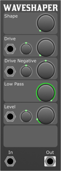
Overview
A Waveshaper transforms the shape of an audio waveform by applying a non-linear distortion process. This process can add harmonics, change timbres, and create entirely new sounds from simple waveforms. The module offers extensive control over the distortion characteristics and tone shaping, making it versatile for creating unique textures and sounds.
It is a Distortion.
Parameters
- Shape:
- Controls the curvature of the waveform transformation. This parameter adjusts how the input signal is bent or reshaped, affecting the harmonic content and texture of the output signal.
- Drive:
- Sets the amount of signal amplification before it is processed by the waveshaping curve. Increasing the drive will introduce more distortion and harmonics.
- Drive CV Attenuverter:
- Allows the modulation of the Drive parameter with an external CV, effectively modulating the drive amount with an external control voltage (CV) source.
- Difference:
- Modifies the symmetry of the waveshaping algorithm to emphasise or de-emphasise the difference between the positive and negative signals, introducing even harmonic tonal variations.
- Difference CV Attenuverter:
- Allows the modulation of the Difference parameter with an external CV, providing dynamic control over the tonal variations introduced by the Difference setting.
- Tone:
- A tone-shaping control that adjusts the balance between low and high frequencies in the output signal. This can be used to smooth out harsh edges or to brighten the sound.
- Level:
- Controls the output volume of the module. This is useful for maintaining consistent levels when using extreme waveshaping settings that might otherwise increase the signal amplitude significantly.
- Level CV Attenuverter:
- Provides an attenuation or inversion of the CV signal applied to the Level parameter, offering dynamic control over the output volume.
- Drive:
- Accepts a CV signal to modulate the Drive parameter dynamically.
- Difference:
- Accepts a CV signal to modulate the Difference parameter, allowing for dynamic changes to the tonal variations.
- Level:
- Accepts a CV signal to modulate the output level, providing dynamic volume control.
- Signal In:
- The audio input for the waveshaping process. Connect an oscillator, another module's output, or any audio source here.
Outputs
- Signal Out:
- The output of the Waveshaper module. This carries the processed signal, now altered according to the waveshaping parameters and modulation inputs.
Usage Tips
- Experiment with different input waveforms to see how the Waveshaper affects them. Simple waveforms like sine waves can be transformed into complex sounds.
- Utilise the Drive AC Attenuverter and Difference CV inputs for dynamic modulation. These can add movement and evolution to the sound over time.
- The Tone control is essential for fitting the waveshaped sound into a mix. Use it to brighten or mellow the sound as needed.
- Be mindful of output levels, especially when using high Drive settings, as the signal can get very loud. Use the Level control to manage the overall output.
Clock
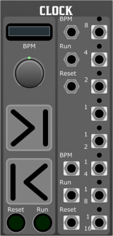
Overview
The Modular Synth Clock Module is a versatile timekeeping module designed to provide precise control over the tempo of your modular synthesiser. It offers various features to manipulate the clock signal, allowing for synchronisation with other modules and external gear. Nudge buttons can be used to help synchronise the clock with other elements in your setup.
Features
- BPM Control:
- BPM Textbox: Input field for entering the desired beats per minute (BPM).
- BPM Knob: A rotary knob for fine-tuning the BPM.
- Clock Manipulation:
- Nudge Forward: Adjust the clock slightly ahead.
- Nudge Backward: Adjust the clock slightly behind.
- Reset: Resets the clock to the beginning of the sequence.
- Run: Controls the overall clock running state.
- Clock Outputs:
- Clock Out 8, 4, 2, 1, 1/2, 1/4, 1/8, 1/16: Outputs clock signals with different divisions.
Interface
- BPM Section
- BPM Textbox:
- Allows the user to enter the desired BPM numerically. This can be handy when manually syncing to other devices or DJ software.
- BPM Knob:
- A rotary control for adjustment of the BPM.
- Clock Manipulation Section
- Nudge Forward:
- Adjusts the clock slightly ahead. This can be useful for manually syncing to other devices or DJ software.
- Nudge Backward:
- Adjusts the clock slightly behind.
- Reset:
- Resets the clock to the beginning of the sequence.
- Run:
- Starts or stops the clock.
- BPM:
- Accepts external control for BPM setting. Uses a 1V/Oct scale, with 0V being C-3 2.044Hz, 122.64 bpm. This allows for the bpm signals to be connected to LFO and delays for synced effects.
- Run:
- Starts or stops the clock externally. This is passed to the run output.
- Reset:
- Resets the clock externally.
Outputs
- BPM:
- Outputs the current BPM for external monitoring. Uses a 1V/Oct scale, with 0V being C-3 2.044Hz, 122.64 bpm. This allows for the bpm signals to be connected to LFO and delays for synced effects.
- Run:
- Outputs the current running state of the clock.
- Reset:
- Outputs a trigger when the clock is reset.
- Clock Out 8, 4, 2, 1, 1/2, 1/4, 1/8, 1/16:
- Outputs clock signals with different divisions corresponding to the selected tempo.
Usage Tips
- Set the desired BPM using the BPM Textbox or BPM Knob.
- Use the Run input to start or stop the clock.
- Utilise the Reset input to reset the clock.
- Nudge Forward and Nudge Backward can be used for fine adjustments to the clock.
- Monitor the BPM, Run, and Reset outputs for external synchronisation.
Chance

Overview
A Bernoulli Gate is a probabilistic gate module for a modular synthesiser. With each incoming gate or trigger at its input, it generates an output at either output A or output B based on a defined probability. This can be particularly useful for creating randomised rhythmic and melodic patterns.
Front Panel Controls:
- Probability Knob:
- This knob adjusts the probability from 0% to 100% for the gate or trigger to be sent to output A.
- When set to 0%, the gate will always go to output B.
- When set to 100%, the gate will always go to output A.
- Intermediate values will adjust the probability accordingly.
- Probability CV Attenuverter:
- This control allows for external modulation of the probability parameter.
- Turning clockwise from the centre increases the modulation amount, while turning counter-clockwise decreases the modulation amount (or inverts it).
I/O Ports:
- Probability CV Input:
- Accepts a CV (Control Voltage) signal to modulate the probability parameter.
- This input is affected by the Probability CV Attenuverter.
- In:
- This is the gate or trigger input. Whenever a gate or trigger is detected at this input, the Bernoulli Gate will decide which output to send it to based on the probability setting.
- Output A:
- Outputs the incoming gate or trigger based on the defined probability.
- Output B:
- If the gate doesn't go to Output A, it will be sent to Output B.
Typical Usage:
- Rhythmic Variations: Connect a regular clock or rhythmic gate pattern to the "In" port and get varied rhythmic patterns at outputs A and B.
- Melodic Variations: By connecting the outputs A and B to different sound sources or sequences, you can create randomised melodic or harmonic variations.
- Dynamic Modulation: By feeding a modulating CV signal into the Probability CV Input, you can get dynamic changes in the probability, leading to evolving rhythmic or melodic patterns.
Tips:
- Experiment with different CV sources for the Probability CV Input for evolving or rhythmic changes in probability.
- Combining outputs with other logic modules can further enhance the rhythmic complexity.
Dust

Overview
Produces random impulses, with a density parameter controlling the rate of impulses. The output is monophonic. Can be used as an audio generator, and a source of triggers, often called violet noise.
Parameters:
- Density:
- Range: 0 to 10
- Description: Adjusts the intensity or amplitude of the violet noise output. At 0, the output is essentially silent. As you increase the density, the amplitude of the violet noise becomes louder.
- Density CV Attenuverter:
- Description: Controls the amount and polarity of voltage control modulation applied to the Density parameter from the Density CV input. When set to its midpoint (0), no modulation is applied. Turning clockwise introduces positive modulation, while counter-clockwise introduces negative modulation.
- Density CV:
- Description: Accepts a control voltage signal to modulate the Density parameter. The depth and polarity of this modulation are determined by the Density CV Attenuverter.
Outputs:
- Out:
- Description: Delivers the generated violet noise signal.
Usage and Applications:
- Sound Design: Violet noise's emphasis on higher frequencies can be used to create airy, shimmering textures or abrasive, high-frequency content.
- Modulation Source: Use the violet noise as a modulation source to create evolving and unpredictable modulations, especially for parameters that can benefit from higher frequency content.
- Experimental Effects: Due to its unique frequency profile, violet noise can be used in experimental setups, especially in conjunction with filters, resonators, or other spectral processing modules.
- Ambience & Atmosphere: Create unique atmospheric sounds by blending violet noise with other noise colours or sound sources.
Tips and Tricks:
- Dynamic Modulation: Utilise an LFO or envelope to the Density CV input to create dynamic changes in the violet noise's amplitude, introducing movement and evolution to your patches.
- Filter Exploration: Sending violet noise through a filter and sweeping the cutoff frequency can reveal interesting resonances and harmonics due to the noise's high-frequency emphasis.
- Combining Noise Types: Blend the output of the Violet Noise Module with other noise colours (like white, pink, or blue) to craft complex and rich noise textures.
- Feedback Loops: Introduce the violet noise into feedback loops to create chaotic and unpredictable sonic results. Be careful with levels to avoid damaging your equipment.
Mutes
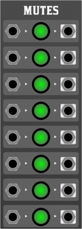
Overview
The Eight-Way Mute Module is a versatile utility module designed for modular synthesisers. It allows users to manually mute or pass through up to eight separate audio or CV signals, making it an essential tool for live performance and studio work. Each channel has a dedicated switch to easily mute or pass through the signal, giving you instant control over your soundscapes.
Features
- 8 independent channels.
- Individual mute switches for each channel.
- Pass-through capability: when unmuted, the signal is passed through unchanged.
- Soft mutes to avoid clicks and pops.
- Compatible with both audio and CV signals.
Front Panel Layout
- Inputs (1-8): These are the individual input jacks for your audio or CV signals. Insert your patch cables here to send a signal into the module.
- Switches (1-8): Each switch corresponds to its respective input. When the switch is in the "up" or "on" position, the signal will pass through the module unchanged. When the switch is in the "down" or "off" position, the signal will be muted.
- Outputs (1-8): These are the individual output jacks. When a signal is unmuted, it will be sent from the corresponding output jack. If muted, no signal will be present at the output.
Usage
- Patch In: Connect the source signals you want to control (e.g., oscillators, envelopes, sequencers) into the desired input jacks on the Eight-Way Mute Module.
- Mute/Unmute: Use the individual switches for each channel to control whether the signal is passed through or muted. Up/On allows the signal through, while Down/Off mutes the signal.
- Patch Out: Connect the output jacks to the desired destination (e.g., mixer, filter, amplifier).
Tips and Tricks
- Performance: The Eight-Way Mute Module is ideal for live performances where you may want to introduce or remove layers of sound on the fly.
- Creating Variations: By connecting various sequencers or modulation sources and selectively muting/unmuting them, you can easily create variations in your patches.
- Signal Routing: Remember, the Eight-Way Mute Module can be used with both audio and CV signals. Try using it to control modulation sources for a dynamic and evolving soundscape.
Notes

Overview
A module with a simple text editor, to store patch notes
Push Toggle Knob

Overview
The Push Toggle Knob is a versatile utility module, providing three parameter elements with CV output; a push button , a toggle button, and a CV knob. This can come in very handy when controlling other modules.
Through
Overview
The Through module is a simple utility module that allows you to pass through audio or CV signals. Each connection can be labeled. This is useful for keeping track of your patch connections.
Quantise
 to desired pitches.
- A single input for the incoming voltage to be quantised.
- A single output that delivers the quantised V/oct voltage.
Front Panel:
- 12 Switch Toggles:
- Resembling a piano keyboard with 7 white and 5 black keys.
- Each switch toggles its corresponding note ON or OFF.
- When ON, the quantiser will allow the input voltage to be rounded to that note.
- When OFF, the quantiser will skip over that note, not allowing the input voltage to round to it.
- Input:
- Labeled "V/oct In."
- This is where you patch the voltage you wish to quantise.
- Output:
- Labeled "V/oct Out."
- This is where you retrieve the quantised voltage to send to other modules.
Operation:
- Connection:
- Connect the voltage source you wish to quantise to the "V/oct In" input.
- Connect the "V/oct Out" output to the desired destination, typically an oscillator's pitch input or another voltage-controlled module.
- Setting the Scale:
- Use the 12 switch toggles to set your desired scale.
- For example, to set a C Major scale, toggle ON all the white keys (C, D, E, F, G, A, B) and toggle OFF all the black keys.
- Quantising:
- When a voltage is fed into the "V/oct In" input, the module will automatically round that voltage to the nearest note that's toggled ON. The quantised voltage will then be sent to the "V/oct Out" output.
Tips:
- To create custom scales or micro-tonal scales, simply toggle ON or OFF the desired notes.
- If all notes are toggled OFF, the quantiser will still output a voltage, but it may not conform to any recognisable musical scale.
- The quantiser works best when fed a continuous or slowly changing voltage, like from an LFO, envelope, or sequencer.
Fifth Step

Overview
Designed to handle multiple voltage octave (voct) inputs and outputs, it provides an efficient means of stepping a pitched Voct signal around the circle of fifths. This module is ideal for creating complex sequences, modulations, and harmonisations in your synthesiser patches.
Features
- Trigger Input: Controls the stepping sequence of the module.
- Six Voltage Octave Inputs (voct1 - voct6): Accepts up to six different voltage control signals for processing.
- Six Voltage Octave Outputs (voct1 - voct6): Outputs the processed voltage control signals.
- Trigger
- Description: This input receives a trigger signal that controls the stepping sequence of the module. Each trigger pulse advances the module to the next step, allowing sequential output changes.
- Type: Trigger signal (typically a gate or pulse).
- Range: 0V (low) to 5V (high).
- Voltage Octave Inputs (voct1 - voct6)
- Description: These inputs accept voltage control signals typically used for pitch control in oscillators or other modulation destinations.
- Type: Control Voltage (CV).
- Range: 0V to 10V.
- Inputs:
- voct1: First voltage octave input.
- voct2: Second voltage octave input.
- voct3: Third voltage octave input.
- voct4: Fourth voltage octave input.
- voct5: Fifth voltage octave input.
- voct6: Sixth voltage octave input.
Outputs
- Voltage Octave Outputs (voct1 - voct6)
- Description: These outputs provide the processed voltage control signals corresponding to the inputs. The module steps through these outputs based on the trigger signal received.
- Type: Control Voltage (CV).
- Range: 0V to 10V.
- Outputs:
- voct1: First voltage octave output.
- voct2: Second voltage octave output.
- voct3: Third voltage octave output.
- voct4: Fourth voltage octave output.
- voct5: Fifth voltage octave output.
- voct6: Sixth voltage octave output.
Usage
- Connecting Inputs: Patch the voltage control signals you want to process into the voct1 to voct6 inputs.
- Triggering: Connect a trigger or gate signal to the trigger input to control the stepping sequence of the module.
- Output Routing: The module will sequentially send the input signals to their corresponding outputs, based on the received trigger pulses.
Random

Overview
The Random Module is a versatile electronic device that samples the voltage level of an internal white noise generator and holds this sampled value for a specified duration. This module is useful in a wide range of applications including music synthesis, audio effect processing, and system testing.
Features
- Internal White Noise Generator: Produces random voltage values, ensuring that each sampling is unique.
- Parameters:
- Min: Sets the minimum voltage level of the white noise.
- Max: Sets the maximum voltage level of the white noise.
- Droop: Determines the rate at which the held voltage decreases over time.
- Inputs:
- Trigger: Initiates the sampling of the white noise generator.
- Outputs:
- Signal Out: Outputs the sampled and held voltage.
Parameters
- Min
- Sets the minimum voltage level that can be produced by the white noise generator.
- Max
- Sets the maximum voltage level that can be produced by the white noise generator.
- Droop
- Controls how the held voltage decreases over time.
- When set to off, the held voltage remains constant. When droop is activated, the held voltage will begin to decrease.
- Trigger
- When a voltage or signal is applied to the trigger input, the module samples the current voltage level from the internal white noise generator and holds it at the Signal Out.
Outputs
- Signal Out
- Outputs the sampled and held voltage level.
- Voltage Range: Between the set Min and Max values.
Typical Use Case
- Set desired Min and Max values to define the voltage range for the white noise generator.
- Adjust the Droop parameter if you want the held voltage to decrease over time.
- Send a trigger pulse to the Trigger input. The module will sample a random voltage from the white noise generator and hold it at the Signal Out.
- The output voltage will remain until another trigger is received or the voltage decreases due to the Droop setting.
Sample & Hold

Overview
The Sample and Hold (S&H) module is a vital utility in a modular synth, used to capture and maintain a specific voltage level for a given period. The module samples an input signal and holds its voltage level until the next trigger event.
Features:
- Switch Droop: When switch droop is enabled, the output voltage will begin to decline at a set rate, imitating an analogue-style S&H.
- Input Trigger: Detects a change in the voltage and prompts the module to sample the source input.
- Source Input: The voltage signal that you want the module to sample.
- Output Signal: Outputs the sampled voltage level, which can be routed to other modules in the synthesiser.
Front Panel Controls:
- Switch Droop Control:
- On/Off Toggle: Enables or disables the switch droop function.
- Input Trigger Jack: This is where you connect the trigger signal. When a rising edge is detected here, the module samples the source input.
- Source Input Jack: Connect the source signal here. This is the signal that will be sampled when a trigger event is detected.
- Output Signal Jack: The sampled and held signal is output from this jack. You can route this signal to other modules for further processing or modulation.
Usage:
- Setup:
- Connect the source signal to the Source Input Jack.
- Connect the triggering signal to the Input Trigger Jack.
- Connect the Output Signal Jack to the desired destination module in your synthesiser.
- Sampling:
- Every time the Input Trigger detects a rising edge, the S&H module will capture the current voltage level of the Source Input and maintain this level at the Output Signal.
- Switch Droop:
- If you desire an analog-style S&H effect where the held voltage slowly decays, turn on the Switch Droop using the On/Off Toggle.
Scope
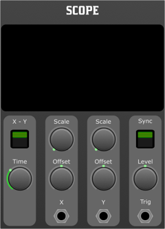
Overview
The two-channel scope module provides visual feedback of your modular synthesiser signals. It's a vital tool for understanding and troubleshooting waveforms in a complex patch. This module offers two inputs, X and Y, to observe different signals simultaneously and comes with various parameters to control the display.
Features
- Two Channels: Allows the observation of two signals simultaneously.
- X-Y Mode (Lissajous Plot): Creates Lissajous figures by plotting the X input against the Y input.
- Sync Input: To synchronise or 'lock' the waveform display.
- Adjustable Parameters: Including Time, X Scale, X Offset, Y Scale, Y Offset, and Sync Level.
Parameters
- X-Y Switch: Toggles between regular dual-channel mode and X-Y Lissajous mode.
- Sync Switch: Enables the synchronisation of the waveform to the sync trigger input.
- Time: Adjusts the time base or "speed" of the scope's sweep. Controls how quickly the waveform is drawn across the screen.
- X Scale: Adjusts the vertical scale of the waveform for the X channel.
- X Offset: Shifts the waveform vertical for the X channel.
- Y Scale: Adjusts the vertical scale of the waveform for the Y channel.
- Y Offset: Shifts the waveform vertically for the Y channel.
- Sync Level: Sets the voltage threshold for the sync trigger. Determines at which voltage level the scope will synchronise.
- X Input: For connecting the signal you want to observe on the X axis/channel.
- Y Input: For connecting the signal you want to observe on the Y axis/channel.
- Sync Trigger Input: Accepts a level for the trigger to synchronise the scope's display.
Operating Instructions
- Standard Dual-Channel Mode:
- Ensure the X-Y switch is in the OFF position.
- Connect the desired signals to the X and Y inputs.
- Adjust the Time, X Scale, X Offset, Y Scale, and Y Offset to view the waveforms clearly.
- If desired, connect a signal to the Sync Trigger Input and turn the Sync switch on. Adjust the Sync Level to ensure proper synchronisation.
- X-Y Mode (Lissajous Plot):
- Toggle the X-Y switch to the ON position.
- Connect the signals you wish to compare into the X and Y inputs.
- Observe the Lissajous pattern. Adjust the X Scale, X Offset, Y Scale, and Y Offset to view the figure clearly.
Tips
- When observing waveforms, starting with a central offset and default scale settings can often provide a clear starting point.
- In X-Y mode, if the Lissajous figure seems too "dense" or "busy," adjust the Time parameter to spread out or compress the figure.
- Use the Sync feature when you want to "freeze" a waveform on the screen, especially when viewing signals with a regular and repeating pattern.
Conclusion
The two-channel scope module is an invaluable tool for both beginners and experts in the modular synthesiser world. By providing real-time visual feedback of the signals in your patches, it can help users understand, troubleshoot, and refine their sound.
Sequencers
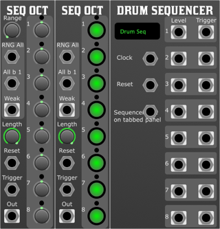
Cv Sequencer
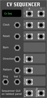
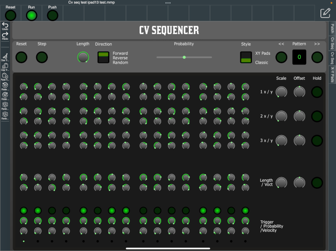
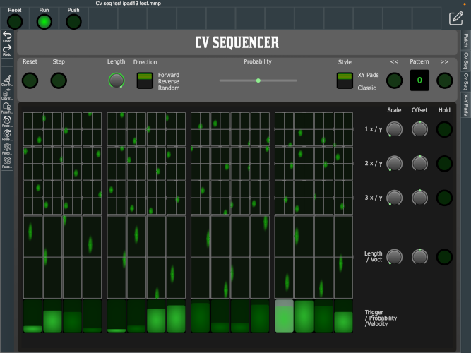
Overview
The 16-Step Sequencer is a versatile tool designed for modular synthesisers, providing advanced control over a sequence of up to 16 steps. Each step can be configured with various parameters including general-purpose CV levels, pitch (V/Oct), length, trigger, probability, and velocity. The sequencer supports up to 100 patterns, which can be easily managed and manipulated using two distinct play surfaces: a classic knob-based interface and a dynamic XY control interface.
Features
Step Parameters
Each step in the sequence can be configured with the following parameters:
- General-Purpose CV Levels (x6): Six customisable CV outputs per step, each with:
- Scale: Adjusts the output range of the CV.
- Offset: Applies a constant value to the CV output, shifting it up or down.
- Hold: If enabled, the current CV value is sustained when no trigger is present.
- V/Oct: Controls the pitch of the note in volts per octave.
- Length: Determines the duration of the step.
- Trigger: Indicates whether the step should produce a gate or trigger signal.
- Probability: Sets the likelihood of the step being played.
- Velocity: Controls the amplitude or dynamic level associated with the step.
Sequence Configuration
- Length: The sequence length can be adjusted from 1 to 16 steps.
- Patterns: Store and recall up to 100 patterns, allowing for complex arrangements and live performance flexibility.
Play Surfaces
- Classic View: A traditional interface featuring knobs for each step, allowing precise manual adjustments of step parameters.
- XY Control View: An interactive surface where each stage can be manipulated via XY controls, offering a more visual and dynamic approach to sequence editing.
- Clock: Drives the sequencer timing. Each clock pulse advances the sequence by one step.
- Reset: Resets the sequence to the first step.
- BPM: Connects to the BPM output of a clock module. This allows the sequencer to adjust the tempo dynamically, ensuring that the length of each step remains proportional when the tempo is changed. This input helps maintain rhythmic consistency even when tempo adjustments are made in real-time.
- Direction: Controls the playback direction of the sequence. The options include:
- Forward: The sequence plays from the first to the last step in order.
- Reverse: The sequence plays from the last step back to the first.
- Random: The sequence steps are played in a random order, providing an unpredictable and evolving pattern.
- Pattern: Selects the active pattern from the available 100 slots. The input range is 0-10V, with each pattern incremented by 0.1V. Patterns are indexed starting from 0, so:
- 0V: Pattern 0
- 0.1V: Pattern 1
- 0.2V: Pattern 2
- ...
- 9.9V: Pattern 99
- RNG (Random Generator): Randomises all parameters for all steps in the sequence. This includes CV levels, V/Oct, length, trigger, probability, and velocity, generating entirely new variations on each step.
- RNG Bar 1: Functions similarly to the RNG input but keeps the first step of the sequence untouched while randomising the parameters of all other steps. This allows for controlled randomness while maintaining a consistent starting point in the sequence.
Outputs
- x1, y1; x2, y2; x3, y3: CV outputs from the XY control surfaces, allowing external modules to interact with the sequence in real time.
- Pattern: Outputs the current pattern number for use in synchronising or controlling other modules.
- EOC (End of Cycle): Outputs a pulse at the end of each sequence cycle.
- Gate: Outputs a gate signal corresponding to the Trigger parameter of the active step.
- V/Oct: Outputs the pitch CV based on the V/Oct parameter.
- Velocity: Outputs the velocity CV, which can be used to control dynamics or modulate other parameters in connected modules.
The sequencer includes a set of menu options that allow for quick manipulation and editing of tracks:
- Clear: Resets the current track, removing all step data.
- Copy Track: Copies the current track configuration, allowing it to be pasted into another pattern or track.
- Paste Track: Pastes a previously copied track into the current pattern or track.
- Rotate Left: Shifts all steps in the sequence one position to the left. The first step moves to the end of the sequence.
- Rotate Right: Shifts all steps in the sequence one position to the right. The last step moves to the beginning of the sequence.
- Randomise All Steps: Randomly assigns values to all steps in the sequence, affecting parameters such as CV levels, V/Oct, and triggers.
- Randomise All Bar First Step: Randomly assigns values to all steps, except the first step of each bar (e.g., steps 1, 5, 9, 13 in a 16-step sequence), introducing variation while maintaining a structured rhythmic foundation.
Usage
- Setting Up the Sequence:
- Connect your clock source to the Clock input.
- Adjust the sequence length to your desired number of steps.
- Configure each step using the knobs or the XY control surface, setting parameters like CV levels, V/Oct, length, and trigger probability.
- Pattern Management:
- Use the Pattern input to select and recall patterns. For precise control, apply a voltage between 0V and 10V, with each 0.1V increment corresponding to a different pattern, starting from index 0. Use the on-board controls for manual pattern selection and management.
- Save your current sequence configuration to one of the 100 available pattern slots for future use.
- Real-Time Control:
- Connect the BPM input to the BPM output of your clock module. This ensures that step lengths remain proportional to the tempo, allowing for seamless tempo adjustments during live performance or studio sessions.
- Set the Direction control to define how the sequence progresses: forward for traditional sequencing, reverse for a mirrored sequence, or random for unexpected variations.
- Apply randomness to your sequence by connecting a modulation source to the RNG input, randomising all parameters across all steps. If you prefer to keep the first step consistent while introducing variation to the rest, connect to the RNG Bar 1 input instead.
- Use the Reset input to restart the sequence from the first step, and adjust the Direction control to dynamically alter playback during performance.
- Using the Menu Options:
- Clear the current track if you need a fresh start.
- Copy Track to duplicate a successful sequence setup, and Paste Track to apply it elsewhere.
- Use Rotate Left and Rotate Right to shift your sequence steps, changing the flow of your sequence.
- Experiment with Randomise All Steps for unexpected and creative variations.
- Apply Randomise All Bar First Step to introduce controlled randomness, perfect for adding subtle variations to your rhythmic patterns.
- Output Routing:
- Patch the sequencer outputs (e.g., x1, y1, Gate, V/Oct) to other modules in your system to integrate the sequencer into your modular setup.
Conclusion
The 16-Step Sequencer is a powerful tool for both studio production and live performance, offering deep control over sequence parameters, flexible pattern management, intuitive menu options, and two interactive play surfaces. Whether you're crafting intricate melodies or generating complex modulations, this sequencer provides the functionality and flexibility needed to expand your creative possibilities.
Drum Sequencer
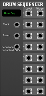
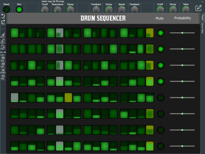
Overview
The 8-Track Drum Sequencer is a versatile module designed for modular synthesisers, providing comprehensive control for rhythmic pattern creation and manipulation. It features both a standard module interface and a dedicated full-screen 8-track sequencer panel. This module is ideal for live performances and studio work, offering intuitive controls and real-time adjustments to enhance your musical expressions. Once the Drum Sequencer module is placed in a patch, a performance surface titled "Drum Seq" is added to the tabs on the right in the patching area. The name of this tab can be changed directly on the module in the patching area.
Features
- Standard Module Interface: Compact UI with essential controls and visual feedback.
- Full-Screen Sequencer Panel: An expanded view for detailed sequencing and performance.
- Inputs:
- Clock: Receives clock signals to drive the sequencer.
- Reset: Resets the sequencer to a predefined start point.
- Outputs:
- 8 Channels: Each channel features a Level and a Trigger output for connecting to other modules.
- Playable Sequencer Panel:
- 8 Horizontal Strips: Each strip represents one of the eight tracks and allows direct interaction with the sequencer.
- 16 Sequencing Cells per Track: Program rhythmic patterns by activating or deactivating cells, setting velocity and probability parameters.
- Mute Button: Quickly mute or unmute individual tracks. When the green indicator is illuminated, the track is active and will emit triggers, else it will not emit triggers and the level output will remain unchanged.
- Probability Slider: Dynamically adjust the probability of notes triggering, facilitating real-time creation of drum fills or rests.
Front Panel Controls
Standard Module UI
- Clock Input Jack: Connect an external clock source to synchronise the sequencer.
- Reset Input Jack: Input for triggering a sequence reset.
- Level Outputs: CV Level output, this is set on an active trigger, and is held until the next.
- Trigger Outputs: Each track emits triggers on active cells. These can be connected to active any module with trigger inputs, such as Drum Sampler & Envelope
Full-Screen Sequencer Panel
- Tracks: Eight horizontal tracks corresponding to each channel.
- Sequencing Cells: Tap or click cells to toggle them on (note plays) or off (note does not play).
- Clicking: Toggles the active state
- Vertical: Adjusts the velocity, the current velocity is sent to the track level output
- Horizontal: Adjusts the probability of a hit occurring.
- Mute Buttons: Each track has a mute button to enable or disable output quickly.
- Probability Slider: Located on each track for adjusting the chance of note playback. Moving the slider to the left decreases the likelihood of a note playing, while moving it to the right increases the likelihood. Releasing the slider resets it to the central position.
Probability Slider Mechanics
The probability slider is a powerful feature for live performance tweaks. It provides the following functionality:
- Decrease Probability: Sliding left from the centre decreases the probability that an active note will trigger, useful for thinning out patterns or creating partial drum rests.
- Increase Probability: Sliding right from the centre increases the probability that an inactive note will trigger, useful for adding unexpected fills or variations.
- Automatic Reset: Upon release, the slider automatically returns to the centre position, restoring the original programmed pattern probabilities.
Applications
- Live Performance: Engage directly with the full-screen panel to dynamically adjust patterns and probabilities during a performance.
- Studio Composition: Utilise the precise controls offered by the standard UI for composing and fine-tuning drum sequences.
Conclusion
The 8-Track Drum Sequencer module combines deep functionality with intuitive design, making it an essential tool for both novice and experienced modular synthesists. Its dual-interface design caters to both focused studio work and dynamic live performance scenarios, offering a wide range of rhythmic possibilities.
Seq Oct Cv

Overview
The Baby 8-Style Eight Stage CV Sequencer is a compact and intuitive module, designed to generate control voltage sequences in a straightforward manner. This module is inspired by the original Baby 8 sequencer, which was a favourite amongst synth enthusiasts for its simplicity and effectiveness.
Features:
- Eight Steps: Individually adjustable steps for customised sequences.
- Variable Range: Adjust the overall voltage range of your sequence.
- Selectable Length: Choose the number of active steps in the sequence.
Parameters:
- Step 1-8: These knobs individually control the voltage level for each of the eight steps in the sequence.
- Range: Determines the overall range of voltage the sequencer can output.
- Length: Choose how many of the 8 steps are active in the sequence. Turning this knob to the right will increase the number of active steps.
- RNG All: When a trigger is received, it randomises all eight steps.
- RNG All but Step 1: Randomises all steps except for the first one.
- Reset: When a trigger is received at this input, the sequencer will immediately return to the first step.
- Trigger: Input to advance to the next step in the sequence.
Outputs:
- CV Out: Outputs the control voltage of the currently active step.
- EOC. End of cycle triggered when sequence resets to the initial position.
Getting Started:
- Connect the sequencer's CV Out to the desired module you wish to control, e.g., a VCO's pitch input.
- Adjust the Range knob to set the desired voltage range for the entire sequence.
- Using the Step 1-8 knobs, set the individual voltage levels for each step in the sequence.
- Rotate the Length knob to select how many steps will be active in the sequence.
- Connect a clock source to the Trigger input to step through the sequence at a fixed rate. Each clock pulse will advance the sequence by one step.
- To randomise the sequence, send a trigger to the desired RNG input (e.g., RNG All, RNG All but Step 1, or RNG Odd Steps).
- To reset the sequence to the first step, send a trigger to the Reset input.
Tips and Tricks:
- For evolving sequences, periodically send triggers to the RNG inputs to keep the sequence fresh and unpredictable.
- Connect the CV Out to parameters beyond pitch, such as filter cutoff or effect depth, to create dynamic modulations.
- By limiting the sequence length and experimenting with the step settings, you can craft unique rhythmic patterns and motifs.
Seq Oct Trig

Overview
The 8-Stage Trigger Sequencer is designed to sequentially output triggers across 8 distinct stages based on various input triggers and conditions. The sequencer offers flexibility with adjustable range and sequence length parameters.
Front Panel Controls
- Switches (Step 1-8): These represent each of the 8 steps in the sequence. Flipping a switch will activate or deactivate its corresponding step.
- Length: A knob to adjust the number of active steps in the sequence, allowing sequences shorter than 8 steps if desired.
- RNG ALL: When a trigger is received at this input, the sequencer will randomly generate a new sequence for all 8 steps.
- RNG ALL BUT STEP 1: Randomises all steps except for the first. Step 1 remains as set by its switch.
- RESET: When a trigger is received at this input, the sequencer will reset back to step 1.
- TRIGGER: This input advances the sequencer by one step. If the sequencer is at the last step and receives a trigger, it will loop back to the first step (or as defined by the LENGTH parameter).
Outputs
- EOC. End of cycle triggered when sequence resets to the initial position.
- TRIGGER OUT: Outputs a trigger signal corresponding to the current active step in the sequence.
Operation
Basic Usage
- Setting Up a Sequence:
- Flip the switches corresponding to the steps you want to be active in your sequence.
- Adjust the LENGTH knob if you want a sequence shorter than 8 steps.
- Running the Sequence:
- Send a continuous series of triggers to the TRIGGER input. The sequencer will advance by one step with each received trigger.
- The TRIGGER OUT will output a trigger signal whenever an active step is reached.
Randomisation
- Sending a trigger to any of the randomisation inputs (RNG ALL, RNG ALL BUT STEP 1, RNG ODD STEPS) will generate a new sequence pattern based on the conditions of that particular input.
Resetting
- Sending a trigger to the RESET input will force the sequencer back to the first step, or the beginning of the set sequence length.
Tips and Tricks
- Creating Evolving Sequences: By frequently sending triggers to the randomisation inputs, you can create sequences that evolve and change over time.
- Syncing with Other Modules: Connect the TRIGGER OUT to other modules in your setup to synchronise operations based on the sequencer's active steps.
- Skip Steps: If you want to skip certain steps in a sequence, simply flip the switch for that step to its off position. Adjusting the LENGTH knob will also enable you to define sequences of specific lengths.
Shift

Overview
The Eight Stage Shift Register captures a series of signal values based on incoming triggers and produces a sequential output from each of its eight stages. This module can be used for creating evolving sequences, random patterns, or other interesting rhythmic and tonal structures.
- Trigger: An input for trigger signals. Every time this input receives a trigger, the shift register reads the signal input and shifts its content.
- Signal: This is where you feed the signal that you want to be read by the shift register.
Outputs:
- Stage 1 - Output for the first stage.
- Stage 2 - Output for the second stage.
- ...
- Stage 8 - Output for the eighth stage.
Each stage output will produce the signal value that was inputted (via the SIG input) n triggers ago, where n is the stage number.
Operation:
- Initial State: When the module is powered on or reset, all stages are empty (usually outputting a 0V or low state).
- Shift Operation: Upon receiving a trigger at the TRIG input, the shift register captures the current value from the SIG input into the first stage. At the same time, it shifts the current values of stages 1 through 7 to stages 2 through 8 respectively. The value in stage 8 is discarded.
Example:
- Before Trigger: Stage1 = 2V, Stage2 = 3V, ...
- Signal Input at the time of Trigger = 4V
- After Trigger: Stage1 = 4V, Stage2 = 2V, Stage3 = 3V, ...
Use Cases:
- Creating Sequences: By sending a rhythmic series of triggers and varying the signal input, the user can craft a sequential pattern that gets outputted across the 8 stages.
- Random Patterns: Feeding a noise source or random voltage into the SIG input and triggering it at regular or irregular intervals will produce unpredictable sequences.
- Feedback Loops: Patching one or more of the stage outputs back into the SIG input can generate evolving feedback loops or patterns.
Switch 1x8

Overview
The 1x8 Switch Module is designed for modular synthesisers, offering the capability to route a single input signal to any of eight outputs. It provides versatile signal distribution within a modular setup, allowing for dynamic signal routing.
Parameters
- Length:
- Defines the number of outputs (from 1 to 8) over which the module will cycle.
- Position:
- Specifies the current output being addressed, ranging from 1 to 8.
- Signal In:
- The input signal that will be routed to the selected output.
- Position Offset:
- Adjusts the current position by the input value. Positive values move the position forward, while negative values move it backward.
- Reset:
- When triggered, resets the position to 1.
- Trigger:
- Advances the current position by one. When the position exceeds the length parameter, it wraps back to 1.
Outputs
- Signal Outputs 1-8
- The eight output jacks where the input signal can be routed.
- EOC (End of Cycle):
- Sends a trigger signal when the module cycles through the defined length and returns to the first position.
Usage
This module is ideal for sequential signal routing, creating evolving sound textures by cycling through different effects or signal paths. It can be used for rhythmic variations, sequential switching, or controlled signal distribution.
Switch 8x1

Overview
The 8x1 Switch Module offers the capability to select from eight input signals and route the chosen signal to a single output. It enables complex signal selection within a modular synthesiser setup, facilitating dynamic signal merging.
Parameters
- Length:
- Sets the number of inputs (from 1 to 8) among which the module can select.
- Position:
- Determines the current input being routed to the output, with a range from 1 to 8.
- Signal Inputs 1-8:
- The eight input jacks where the signals to be selected are connected.
- Position Offset:
- Modifies the current position based on the input value. Positive inputs advance the position, whereas negative inputs decrease the position.
- Reset:
- Resets the position to 1 upon receiving a trigger signal.
- Trigger:
- Increments the position by one, cycling through the inputs. Upon reaching the last input as defined by the length parameter, it loops back to the first input.
Outputs
- Signal Out:
- The output jack where the selected input signal is routed.
- EOC (End of Cycle):
- Outputs a trigger signal when the position has cycled through all selected inputs and returns to the starting position.
Usage
The 8x1 Switch Module is suited for dynamic input selection, enabling users to switch between different sound sources or modulation signals. It's particularly useful for live performances, where quick selection and routing of signals are essential, as well as for automated signal switching in complex patches.
Mixers
Alpha Mixer
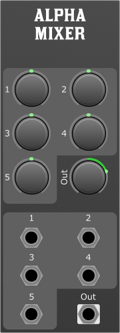
Overview
The 5-Channel General Purpose Mixer is a versatile module designed for modular synthesiser systems. It provides a straightforward way to combine up to five input signals, allowing for intricate sound design, signal routing, and modulation. This document serves as the official guide for installing, operating, and integrating the mixer into your modular setup.
Features
- 5 Input Channels: Each channel accepts an audio or CV signal for mixing.
- Channel Attenuverters (1-5): Control the amplitude and polarity of each input signal.
- Master Output Attenuverter: Adjusts the amplitude and polarity of the combined output signal.
- Independent Inputs (1-5): Dedicated input jacks for each channel.
- Single Output (Out): The combined signal from all channels is sent out of this output.
Front Panel Controls
- Channel Attenuverters (1-5): These knobs control the level of each input signal. Turning the knob clockwise increases the level; turning it counter-clockwise decreases the level and eventually inverts the signal when going past the midpoint.
- Out Attenuverter: Similar to the channel attenuverters, this controls the overall output level and can invert the signal.
- Channel Inputs (1-5): The jacks for input signals. Each channel can independently process audio or CV.
- Output (Out): The jack providing the mixed signal from all active inputs.
Operation
- Connect your source signals to the inputs of channels 1-5.
- Adjust the attenuverters for each channel to set the desired levels.
- Use the Out Attenuverter to adjust the overall level of the mixed output.
- The mixed signal is now ready to be sent from the output to other modules or equipment.
Mixer 8
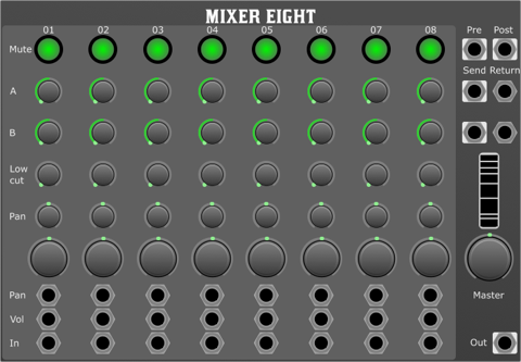
Overview
8-Channel Mono In Stereo Out Mixer designed for modular synthesisers. This mixer is a versatile and powerful solution for combining multiple mono signals into a stereo mix within your modular synth setup.
Features
- 8 mono input channels with mute switch, 2 auxiliary sends, low cut filter, pan, volume, and signal inputs. All polyphonic channels are summed to mono on input.
- Master section with master volume control, RMS meter, stereo send and return ports, and stereo master output.
Front Panel Controls
- Channel Strip
- Mute Switch: Individual mute switches for each channel.
- Auxiliary Sends (2 per channel): Send your signal to external effects or other modules.
- Low Cut Filter: Adjustable low cut filter to tailor the low-frequency response and clean up mixes.
- Pan Control: Adjust the channel's placement in the stereo field.
- Level Control: Set the input level of the channel.
- Inputs (Pan, Volume, Signal): Connectors for pan & volume CV
- Signal input all polyphonic channels summed to mono.
- Master Section
- Master Volume Control: Adjusts the overall output level.
- RMS Meter: Provides a visual indication of the average signal level.
- Stereo Send and Return Ports: Connect external stereo processors or modules.
- Stereo Master Output: Main stereo output for connecting to your amplifier or recording device.
Cross Over

Overview
The Cross Over Module is a state-of-the-art signal processing unit for modular synthesisers that employs 4th-order Linkwitz-Riley filters to split an input signal into high and low-frequency components. This module is ideal for precise frequency separation in complex synthesis setups or for multi-amped speaker systems.
Features
- Frequency: Determines the cutoff frequency where the signal is divided.
- Frequency CV Attenuverter: Controls the amount and polarity of the modulation applied to the cutoff frequency from an external CV source.
- Frequency CV Input: Accepts CV for modulating the cutoff frequency.
- Signal Input: Receives the audio signal to be processed.
- Low Output: Emits the low-frequency component of the input signal below the cutoff frequency.
- High Output: Emits the high-frequency component of the input signal above the cutoff frequency.
Controls
- Frequency Knob: Sets the cutoff frequency of the filters.
- Frequency CV Attenuverter Knob: Adjusts the depth and direction of the CV influence on the cutoff frequency.
Usage
- Connect the audio signal to the Signal Input.
- Connect the Low and/or High Outputs to subsequent modules or outputs.
- Adjust the Frequency knob to set the desired crossover point.
- To modulate the frequency, connect a CV source to the Frequency CV Input and use the attenuverter to adjust the modulation depth and polarity.
Applications
- Frequency-specific processing, where different effects are applied to highs and lows.
- Multi-speaker sound systems requiring precise frequency routing.
Notes
- Linkwitz-Riley filters guarantee a phase-coherent crossover, ensuring a seamless transition between the high and low paths.
- The Frequency CV Attenuverter can be used for creative frequency sweeps or dynamic filtering effects.
DSP Building Blocks
Each module is distinguishable by a unique colour code on its panel, simplifying identification and selection during use. Unlike typical modules found in modular synthesisers, these units delve deeper into the realm of signal processing, paralleling the core elements found in specialised software such as Reaktor, MaxDSP, or Pure Data.
Intended for developers and experimenters who seek unadulterated signal manipulation, these modules stand as singular units of DSP. They operate without altering the integrity of inputs or outputs through sanitisation or filtering, delivering a raw and authentic processing experience.
The creation and refinement of these modules have been extensively supported by the "DSP Building Blocks" package. This foundational package has played a pivotal role in the development and inclusion of the versatile modules you will engage with.
As you embark on your journey through the DSP Module Framework, this introduction will be followed by detailed descriptions and operational instructions to assist you in harnessing the full potential of the DSP modules at your disposal.
All Pass Filter
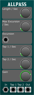
Overview
The AllPass Filter module is a versatile component designed for use in modular synthesisers, offering unique phase shift characteristics that affect the frequency response of audio signals passing through it. Unlike traditional filters that primarily affect amplitude, an AllPass Filter modifies the phase of different frequencies by varying amounts, creating subtle to dramatic tonal changes without significantly altering the signal's volume. This module can be particularly useful for creating phasing effects, spatial effects, reverbs and enhancing stereo imaging.
Controls
- Length:
- Controls the delay length of the internal buffer of the AllPass Filter, which directly influences the phase shift characteristics. Increasing the length will result in a more pronounced phase shift effect across frequencies.
- Max Excursion:
- Determines the maximum range of modulation applied to the filter's length, based on the input from the Excursion CV. This allows dynamic control over the phase shift effect, enabling more expressive and evolving soundscapes.
- Tap 1 Position:
- Sets the position within the internal buffer from which Tap 1 output is derived. This parameter allows you to extract a phase-shifted version of the input signal at a specific point in the filter's delay line, offering creative possibilities for parallel processing and effect layering.
- Tap 2 Position:
- Similar to Tap 1 Position, this sets the position for Tap 2 output. This additional tap provides further flexibility in sound design, enabling users to access another uniquely phase-shifted signal from a different point in the delay line.
- Gain:
- Adjusts the internal feedback gain of the AllPass Filter, which can influence the intensity and character of the phase shift effect. Higher gain settings can result in more pronounced phase shifts, while lower gain settings can produce subtler, more transparent phase shifts.
Inputs
- Signal:
- The primary audio input for processing through the AllPass Filter. This can be any audio signal from oscillators, other filters, or external sources.
- Excursion CV:
- Control Voltage input for dynamically modulating the Max Excursion parameter. By applying an external CV signal, users can achieve time-varying effects that respond to other elements of the modular system.
Outputs
- Signal:
- The main output of the module, providing the processed signal with its phase altered by the filter's parameters. This output can be used as a direct replacement for the original signal or mixed back in for phase-related effects.
- Tap 1:
- Outputs a signal tapped from the position specified by the Tap 1 Position parameter. This offers a unique version of the input signal with its own phase characteristics.
- Tap 2:
- Similar to Tap 1, this outputs a signal from the position specified by the Tap 2 Position parameter, providing an additional layer of sonic possibilities.
Usage Tips
- Experiment with varying the Length and Max Excursion parameters in real-time to create dynamic, evolving textures.
- Utilise the Tap 1 and Tap 2 outputs to layer phase-shifted signals with the original, or with each other, for complex rhythmic or textural interplays.
- Consider the use of modulation sources like LFOs, envelopes, or sequencers to automate the Excursion CV and Gain parameters for more lively and responsive soundscapes.
- The AllPass Filter can be particularly effective in stereo patches, where subtle phase differences can be exploited to enhance the width and depth of the sound field.
Delay Line
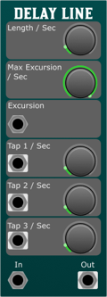
Overview
- Adjustable Delay Length: Control the duration of the delay effect, from very short, creating phasing effects, to longer delays for echo-like effects.
- Max Excursion: Sets the limit for the modulation depth of the delay time, allowing for vibrant chorus and vibrato effects.
- Dual Tap Outputs: Tap 1 and Tap 2 positions can be independently adjusted, providing two distinct delay times from the same input signal for complex rhythmic patterns.
- CV Control for Excursion: Offers real-time modulation capabilities of the delay time through an external control voltage (CV) source.
Controls
- Length:
- Determines the base length of the delay line. It's adjustable to accommodate various musical timing needs, from tight slap-back echoes to longer, spacious delays.
- Max Excursion:
- Specifies the maximum amount by which the delay time can be modulated. This feature is particularly useful for creating dynamic effects that respond to playing intensity or other modulation sources.
- Tap 1 Position:
- Sets the delay time for Tap 1 output, allowing users to extract a delayed signal at a specific point in the delay line. Ideal for creating echoes or doubling effects.
- Tap 2 Position:
- Similar to Tap 1, but sets the delay time for Tap 2 output. This can be used in conjunction with Tap 1 to create intricate polyrhythmic patterns or to enhance spatial imaging.
- Signal:
- The main audio input for processing through the delay line. Accepts signals from other modules in the synthesiser setup.
- Excursion CV:
- Control Voltage input for dynamically modulating the delay time. The depth of the modulation is limited by the Max Excursion parameter. This can be sourced from LFOs, envelope generators, sequencers, or any CV source.
Outputs
- Signal:
- Outputs the processed signal with the applied delay effect. This is the sum of the original signal and the delayed signals from Tap 1 and Tap 2, according to their set positions and the overall Length and Max Excursion settings.
- Tap 1:
- Provides an output for the signal delayed according to the Tap 1 Position parameter. This output allows for creative routing options, such as feeding it into other modules for further processing.
- Tap 2:
- Similar to Tap 1, this output delivers the signal delayed according to the Tap 2 Position parameter. It can be used independently or in conjunction with Tap 1 to explore complex sound design possibilities.
Usage Tips
- Experiment with different Excursion CV sources to create dynamic, evolving delay effects that respond to your playing or sequenced patterns.
- Utilise the dual tap outputs to create stereo delay effects by panning Tap 1 and Tap 2 to opposite sides.
- Combine the Delay Line Module with modulation sources, like LFOs or envelope generators, to modulate Tap positions for unique rhythmic effects.
One Pole LPF

Overview
The One Pole Low Pass Filter (OPLPF) module for modular synthesisers is designed to shape your sound by attenuating frequencies above a specified cutoff point, allowing lower frequencies to pass through. This process adds warmth and depth to your audio signal, making it a fundamental tool for sound design in modular synthesis environments.
Controls
- Cutoff Frequency (Cutoff)
- This knob adjusts the frequency at which the filter starts to attenuate higher frequencies. Turning the knob clockwise increases the cutoff frequency, allowing more high frequencies to pass through. Turning it counterclockwise lowers the cutoff frequency, restricting more high frequencies.
- Cutoff CV Attenuverter
The Cutoff CV Attenuverter controls the depth and polarity of the modulation applied to the cutoff frequency by the Cutoff CV input. Turning it clockwise applies positive modulation, increasing the cutoff frequency in response to the CV signal. Turning it counterclockwise applies negative modulation, decreasing the cutoff frequency in response to the CV signal.
- Signal Input
- This is where you input the audio signal you wish to process. The module filters this signal according to the cutoff frequency and CV modulation settings.
- Cutoff CV
- Accepts control voltage (CV) signals for dynamic modulation of the cutoff frequency. The effect of the incoming CV on the cutoff frequency can be adjusted with the Cutoff CV Attenuverter.
Outputs
- Signal Output
- Outputs the filtered audio signal. The characteristics of this signal depend on the settings of the cutoff frequency and the modulation applied through the Cutoff CV input.
Usage Tips
- Dynamic Modulation: Utilise the Cutoff CV Input with an LFO or envelope generator to create dynamic changes in your sound, such as rhythmic pulsations or evolving textures.
- Warmth and Depth: Lowering the cutoff frequency can add warmth to bright or harsh sounds, making them blend more smoothly into your mix.
- Experiment with Sources: Try filtering different types of sound sources, from oscillators to noise generators, to explore a wide range of sonic possibilities.
Polyphony
In the realm of modular synthesis within the hardware domain, achieving polyphony is often a costly endeavour. This is typically because it necessitates the replication of each module for every additional voice or channel. However, the landscape shifts dramatically when we enter the virtual domain, where such complexity becomes almost effortless. Here, every virtual cable has the capacity to carry up to 16 distinct channels, and modules are designed to automatically conform to the number of channels received at their inputs. It is usual for the signal input that is subject to transformation, to set the channel count automatically. Furthermore, control voltage (CV) inputs are polyphonic as well, permitting the modulation of each channel on an individual basis. In instances where a CV input is monophonic (carrying only a single channel) it will uniformly modulate all channels.
A small collection of utility modules are provided to assist in the creation of polyphonic patches. These modules are Merge, Split, Add and Sum.
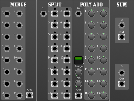
- Merge: This module combines multiple signals into a single polyphonic signal. It is useful for combining the outputs of multiple oscillators into a single polyphonic signal, or for combining the outputs of multiple sequencers into a single polyphonic control signal.
- Split: This module splits a polyphonic signal into multiple signals. It is useful for splitting a polyphonic control signal into multiple signals, or for splitting a polyphonic audio signal into multiple signals.
- Add: This module allows the manual manipulation of a polyphonic signal and is a good source for controlling polyphonic parameters.
- Sum: This module sums multiple polyphonic signals into a single polyphonic signal. It is useful for combining the outputs of multiple oscillators into a single polyphonic signal, or for combining the outputs of multiple sequencers into a single polyphonic control signal.
- PAM: Poly Add Mini, a slimline version of the Poly Add module.
Midi
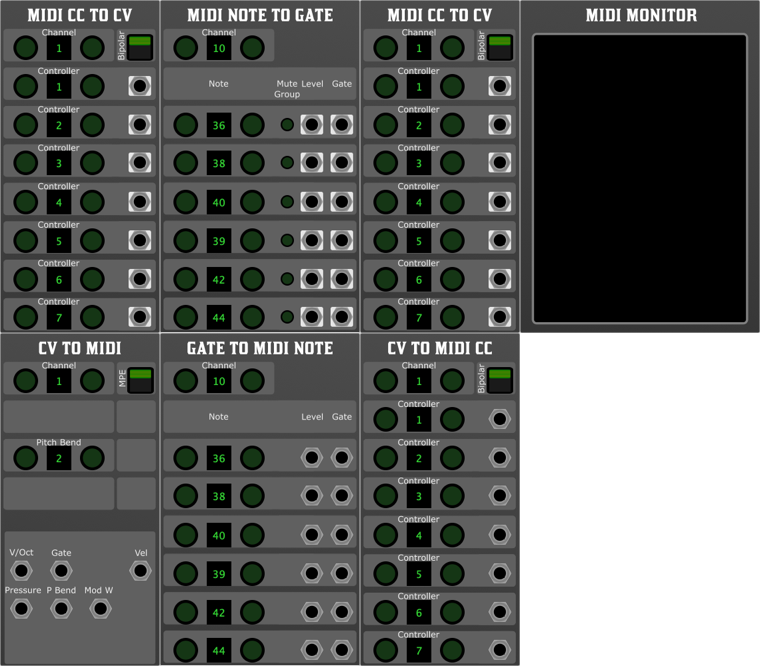
MooMu comes with a set of midi modules for interfacing with both external midi devices and DAW midi routing. It is advised to run as a plugin in a DAW or AUM on iOS to take advantage of these modules.
Midi Minitor
Overview
The MIDI Monitor is a simple tool that provides real-time visualisation of incoming MIDI messages. It does not include any controls, filters, or additional configuration options, making it ideal for straightforward MIDI monitoring and debugging purposes.
Simply place the MIDI Monitor module in your patch to view the MIDI messages being received by your Moomu system. This can be particularly useful for verifying that MIDI data is being transmitted correctly from external devices or software applications.
Midi to CV
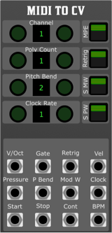
Overview
The MIDI to CV module converts incoming MIDI signals into control voltages (CV) for use within a virtual modular synthesiser. It enables integration between MIDI controllers, sequencers, and other MIDI sources with modular synthesisers by translating MIDI note and control data into voltage-based signals.
Parameters
- Channel:
- Sets the MIDI channel (1-16) that the module responds to. If MPE is selected, it responds to all channels.
- Poly Count:
- Determines the number of polyphonic voices the module generates.
- Pitch Bend:
- Defines the pitch bend range, allowing for smooth pitch modulation. By default this is +- 2 semitones, and +- 48 semitones for MPE
- Clock Multiplier:
- Sets the multiplication factor for the incoming MIDI clock signal, as seen at the Clock output allowing for tempo synchronisation at different rates.
- MPE (MIDI Polyphonic Expression):
- Enables support for MPE-capable controllers, allowing for per-note modulation. This is idea when using the isomorphic keyboard, as provided by the Keys module.
- Retrig:
- Determines whether gates are retriggered when a note is played again without being released.
- Smooth MW (Mod Wheel Smoothing):
- Applies smoothing to the modulation wheel (CC1) data to reduce sudden jumps.
- Smooth Pitch Wheel:
- Applies smoothing to the pitch bend data, preventing abrupt changes.
Outputs
- V/Oct (Voltage per Octave):
- Outputs a control voltage corresponding to the pitch of incoming MIDI notes.
- Gate:
- Outputs a high signal when a note is held and returns low when released.
- Retrig:
- Generates a short pulse each time a note is played, useful for triggering envelopes.
- Velocity:
- Outputs a voltage corresponding to the velocity of the played note.
- Pressure:
- Provides control voltage based on aftertouch or pressure sensitivity from the MIDI input.
- Pitch Bend:
- Outputs a CV representation of the MIDI pitch bend signal.
- Mod Wheel:
- Outputs CV from the modulation wheel (CC1) data.
- Clock:
- Outputs a pulse synchronised to the incoming MIDI clock.
- Start:
- Sends a high pulse when a MIDI start message is received.
- Stop:
- Sends a high pulse when a MIDI stop message is received.
- Continue:
- Sends a high pulse when a MIDI continue message is received.
- BPM:
- Outputs a voltage proportional to the detected MIDI clock tempo.
Midi Note to Gate
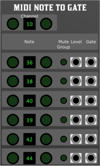
Overview
The MIDI Note to Gate Module is designed to convert MIDI note data into gate and level signals, making it an essential tool for integrating MIDI control with modular synthesisers. With six independent channels, each equipped with flexible note selection and mute grouping, this module provides precision and versatility for triggering envelopes, sequencers, and other modulation sources.
Features
- Six independent channels – Each channel can be assigned to a different MIDI note.
- Double-tap channel selection – Quickly auto-select the desired channel.
- Mute groups – Assign channels to a mute group for easy control over multiple triggers.
- Per-channel gate and level outputs – Provides both a binary gate signal and a variable level output for more dynamic control.
Parameters
- Channel Selection:
- Double-tap to auto-select – Quickly select a channel by double-tapping its control.
- Six channels
- Independent control over six unique MIDI note-to-gate assignments.
- Note selector
- Assign a specific MIDI note to trigger each channel. Double tap to select next received note.
- Mute group assignment
- Assign a channel to a mute group to silence multiple channels simultaneously.
Outputs
Each of the six channels provides:
- Gate Output
- Outputs a high signal when the assigned MIDI note is active.
- Level Output
- Provides a corresponding level signal based on MIDI velocity or user-defined scaling.
Usage
Select a channel by double-tapping its control.
Assign a MIDI note to trigger the gate and level outputs.
Use mute groups to manage groups of channels collectively.
Patch the gate outputs to envelope generators, drum machines or sequencers.
Use the level outputs for dynamic modulation based on MIDI velocity.
This module is ideal for integrating MIDI controllers, drum machines, and DAW sequences into a modular environment, offering precise and expressive control over your patches.
MIDI CC to CV Module
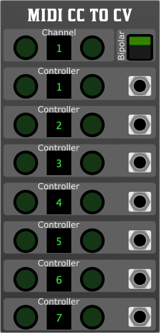
Overview
The MIDI CC to CV Module is designed to convert MIDI Continuous Controller (CC) messages into control voltage (CV) signals for use in modular synthesisers. With six independent output channels, each capable of responding to a designated MIDI CC, this module enables expressive modulation and automation from MIDI sources.
Features
6 Independent CV Outputs – Each output responds to a selected MIDI CC message.
Per-Stage MIDI CC Selection – Configure each of the six channels to respond to a specific CC.
Global MIDI Channel Selection – Assignable to any MIDI channel.
Bipolar Mode – Allows CV outputs to operate in either unipolar (0V to +10V) or bipolar (-5V to +5V) mode.
Precise CV Scaling – Ensures accurate and smooth voltage conversion from MIDI CC values.
Parameters
- Channel
- Sets the global MIDI channel the module listens to. Double tap for auto select
- Accepts values from 1–16.
- Bipolar Mode
- Toggles between unipolar (0V to +10V) and bipolar (-5V to +5V) output.
- When enabled, CC values of 0 correspond to -5V, 64 to 0V, and 127 to +5V.
- MIDI CC Select (Per Stage)
- Each of the six output channels can be assigned a unique MIDI CC number:
- Selects which CC message controls the corresponding output stage.
Outputs
The module provides 6 independent CV outputs, each responding to its assigned MIDI CC.
Usage Example
Select MIDI Channel – Set the module to listen on the desired MIDI channel.
Assign MIDI CCs – Choose which MIDI CC controls each output.
Set Bipolar Mode – Decide whether the outputs should operate in bipolar or unipolar mode.
Send MIDI CC Data – Use a MIDI controller, DAW, or sequencer to send MIDI CC messages.
Patch CV Outputs – Route the generated CV signals to other modules in your system for modulation.
Notes
The module does not generate gate signals; it is purely for CV modulation.
If the assigned CC is not received, the output will remain at its last value.
Ensure your MIDI source is correctly configured to send CC messages on the assigned channel.
Cv to Midi module
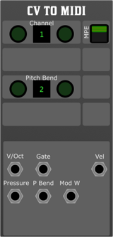
Overview
The CV to MIDI module converts control voltage (CV) signals into MIDI messages, allowing integration between modular synthesis and MIDI-compatible devices or software. It translates pitch, velocity, and expressive modulation into MIDI data, making it ideal for controlling external synths, virtual instruments, and hardware MIDI devices.
Parameters
- Channel
- Sets the MIDI channel (1–16) to which messages are sent.
- MPE (MIDI Polyphonic Expression)
- Enables or disables MPE mode for enhanced per-note expression.
- When enabled, pitch bend, pressure, and modulation apply individually to each note.
- Default: Off
- Needs to be selected on both the transmitter and receiver.
- Pitch Bend Range
- Defines the pitch bend range in semitones.
- Affects how CV pitch changes are translated into MIDI pitch bend messages.
- Default: ±2 semitones, +-48 in MPE mode
- V/Oct (Voltage per Octave)
Accepts a 1V/Oct pitch CV signal.
Converts to MIDI note messages based on the selected channel.
- Gate
- Accepts a gate signal to trigger MIDI note-on and note-off messages.
- A high signal triggers a note-on message; a low signal triggers a note-off message.
- Velocity
- Accepts a CV input to control MIDI velocity (0–127).
- Typically used with an envelope or velocity-sensitive control source.
- Pressure (Aftertouch)
- Converts an input CV signal into MIDI aftertouch messages.
- Useful for expressive modulation in MPE and standard MIDI setups.
- Pitch Bend
- Accepts a bipolar CV signal and converts it into MIDI pitch bend messages
- Scaled according to the Pitch Bend Range setting.
- Mod Wheel
- Converts an input CV signal into MIDI CC#1 (Modulation Wheel) messages.
- Enables CV-based modulation of external MIDI instruments.
Usage Notes
Ensure the module is assigned to the correct MIDI channel for proper routing.
For MPE mode, ensure the receiving synth supports MPE and is configured accordingly.
When using Pitch Bend, set the range appropriately to match the target MIDI instrument.
Use a smooth CV source for pressure and mod wheel inputs to avoid stepped modulation.
This module serves as a powerful bridge between modular synthesis and MIDI-based instruments, offering both standard and expressive MIDI control.
Gate to Midi Note
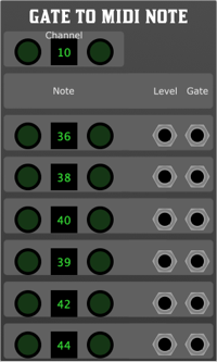
Overview
The Gate to MIDI Note module converts incoming gate signals into corresponding MIDI note messages. It allows for six independent stages, each with its own note selection, offering precise control over MIDI note triggering.
Parameters
- Channel:
- Sets the MIDI channel (1–16) on which the notes will be sent.
- Six Stages (Note Select): Each stage has an independent note selection parameter, determining which MIDI note will be sent when the corresponding gate input is triggered.
- Stage 1–6 Level:
- Receives a control voltage (CV) that can be used to modulate the note velocity.
- Stage 1–6 Gate:
- Triggers the corresponding MIDI note when a gate signal is received. A high gate signal initiates a note-on message, and a low gate signal sends a note-off message.
Functionality
When a gate signal is received at any stage input, the corresponding MIDI note is sent on the specified channel.
The level input can dynamically alter MIDI velocity.
Each stage operates independently, allowing multiple notes to be triggered simultaneously.
Use Cases
Converting gate signals from sequencers or modular synths into MIDI notes for external synthesisers or software instruments.
Creating dynamic MIDI sequences based on modular system triggers.
Enhancing live performance setups by integrating modular and MIDI-based gear.
Cv to Midi

Overview
The CV to MIDI CC module is designed to seamlessly integrate control voltage (CV) signals with your digital MIDI setup, offering precise modulation possibilities for virtual instruments and hardware alike.
Parameters:
- Channel
- Selects the MIDI channel (1–16) for outgoing CC messages.
- Bi-Polar Mode
- Enables conversion of both positive and negative CV signals, centring around 0V. When disabled, only positive voltages are processed.
- Six-Stage CC Number Select
- Allows assignment of up to six different MIDI Control Change (CC) numbers, dynamically mapping incoming CV to multiple MIDI parameters.
- CV Level
- Accepts a control voltage input, which is scaled and converted into a corresponding MIDI CC value based on the selected parameters.
This module is perfect for bridging the analogue expressiveness of modular synthesis with the flexibility of MIDI-based systems, providing enhanced control over soft synths, DAWs, and MIDI-enabled hardware.


 MooMu comes with a set of midi modules for interfacing with both external midi devices and DAW midi routing. It is advised to run as a plugin in a DAW or AUM on iOS to take advantage of these modules.


